Month: June 2025

Planning logic for Optical printer digital control


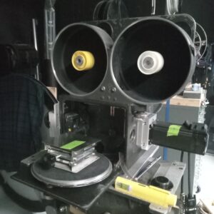
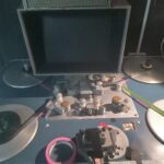
Soon as I have finished some other things here in Rendlesham towers I’m going to get straight onto digitising the controls of the optical printer.

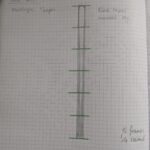
To do this I’ve broken down the functions, basic electrical control functions to 4 PAIRS.

This means there are 2 pairs of wires for the projector and 2 pairs for the camera.

Heres the first version of the logic.
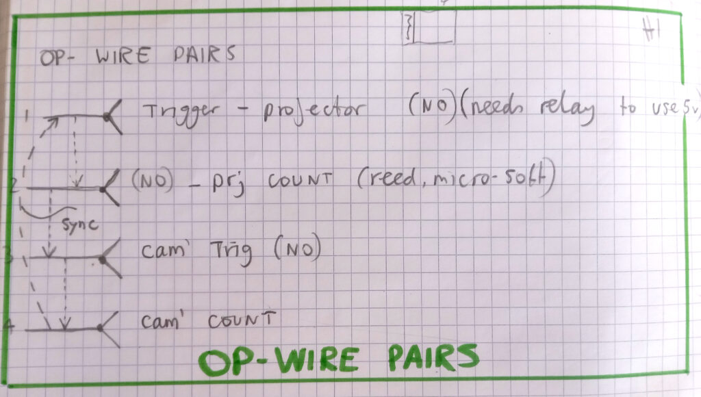


You can read the pairs on the left. The 1st pair is the switch used to trigger tje projector to load a new frame. This can be a momentary push button or a latching RUN button.

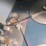
When it gets pressed it sets off a chain reaction, it effectively injects 120v into a relay, this engages a mechanical clutch, this rotates a shaft, this drives the printer mechanism to move 1 new frame in plus toother wheels, etc somewhere in there a micro-switch gets triggered which can be used to make a counter add a number and if its connected to the camera it acts as the PRIMARY device and a new frame will be fired on the camera. If this button is latched to RUN the whole thing will keep moving and you will get a 1 : 1 copy sequence going.

The 2nd pair is the projector count micro-switch.

The 3rd switch pair is the camera trigger. This can also be single frame or RUN. It produces the contact in the last pair for the camera count.

Now, if 2 is connected to 3 we get the sync as described above.

Now heres version 2.
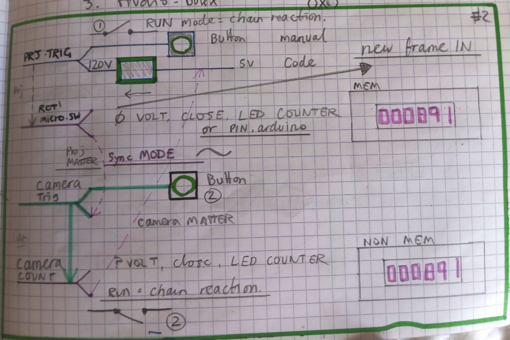
The same thing but with a bit of colour coding. Green for button controls and magenta for SECONDARY, controlled actions.

What is needed, to enhance counting and frame sequence creativity is something like an Arduino or Rpi to do all the counting and maths or rhythms or programming.
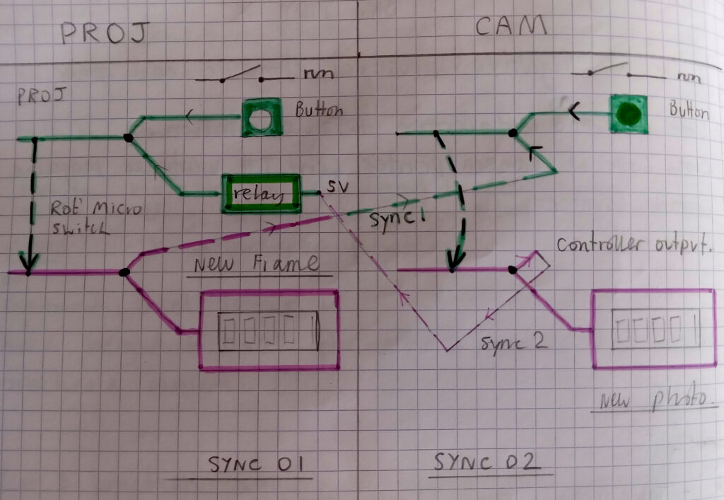


So, to help visualise this I’ve divided the switch pairs into PROJECTOR and CAMERA which stand lef tto right like they do on the actual machine. Its really clear from this now that what we need first is another sync mode where the CAMERA is PRIMARY and the PROJECTOR is SECONDARY.

Because the projector trigger button has 120v across it, I need to add a relay so that this pair can be fired from a digital device like Arduino. Once that is done there can be 2 sync modes.
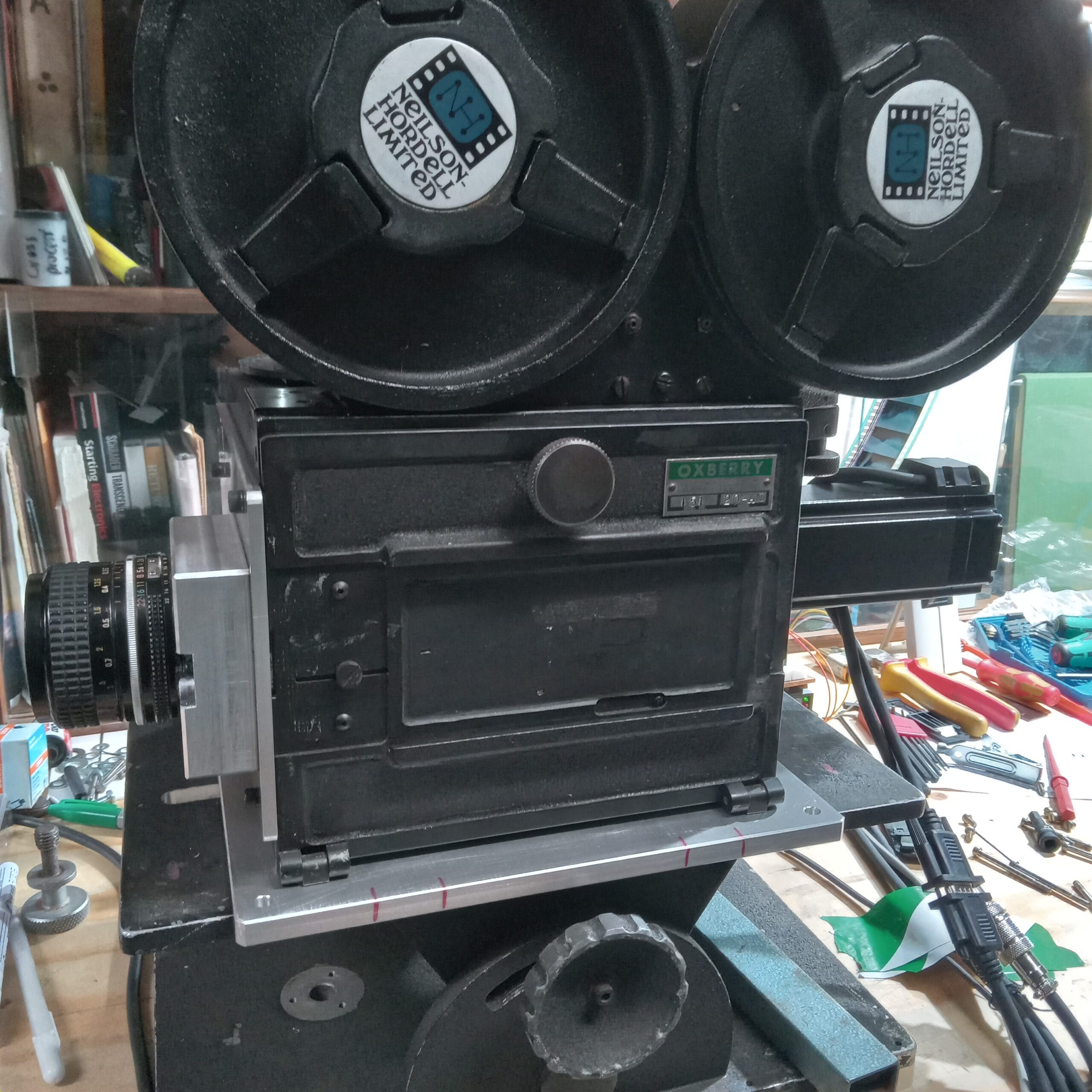
 

Stepper Motor camera drive #02


I’ve been doing a lot of coding for the arduino control of the camera Im calling OX2.

I was considering porting the whole thing over to a RPi so that I could have a keyboard and screen etc to allow more functions based on prompts etc. But seeing as all I need is a X230/IBM or something smaller even, its possible to imagine using this system with the serial monitor?

Instead of writing code and building all the hardware to offer all the functions I’m just using the arduino in PC-usb connected mode and using the serial monitor to do the operation.

After quite a few rewritings Ive landed on a nice set up that offers the following:

1. Single frame always on button.

2. F for forwards and R for reverse camera direction.

3. Select 16 or 35mm, used to instruct footage counter which differs between the guages, ie 40 and 16 frames respectively.

4. Input nunber of frames. Ie, 1 = 1 frame, 24 = 24 frames.
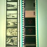
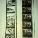
5. B setting, asks for time open in seconds, ie 20 = 20 seconds.
6. H function opens shutter 180 degrees, effectively going into ROTOSCOPE mode. This is very useful for setting up camera-projection.

7. Counters for ‘session’, or lifetime (magazine footage). With resets on both.

TO DO:

8. Speed of steps monitor. The effective shutter speed is best measured ITRW. This is because the maths doesnt really add up. You need to high speed video the mech running in rotoscope mode, and measure the frames in an edit programme. I use Vegas. If the POT input (which controls speed) is mapped to ACTUAL shutter speeds we can use this for displaying shutter speeds in the future.

9. Micro step mode. This is useful if there develop problems with shutter sync. This can and has happened. Despite the motor being closed loop, it doesnt actually have an exact position sensor. You could add one, but the drive is built tightly into mounting hardware and the shaft is not accessible.


10. Getting Arduino to pulse out frame counters for big red LED displays. Note to self, the memory counter can only be volt free, ie fired from a relay.

11. Emergency STOP function if you type in too many frames. This could also go on the big red stop button on the controller.

12. Trigger motion-control job/event. I know I will get around to this, but if we employ simple (and inexpensive) CNC X & Y moving stages for movement of objects we have basically a Go-Motion rig.

13. Time Lapse. This will be easy enough, but be better employed if the whole rig is portable, ie to take outside, and need to build the 36v psu for this and work out way to power TUPS.

14. More a question. Has stepper micro setting been fully explored? Is 1600 per rotation absolutely the best setting?

Activity June

optical sound

I’ve been playing with Matts (https://sixteenmillimeter.com) brilliant Processing sketch for optical sound wave forms using chatGPT to do all the code rewriting I cant do. An amazingly pleasurable experience which as well as leaving me elated also made me consider the ethical dimension to this?


Heres the sketch. You must move the wav file to the data folder in the sketch folder for this to work.

PROC01

This work is part of ongoing research into the optical sound track, its graphical properties, methods, techniques, technologies and history.

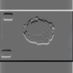
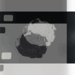
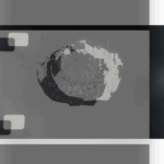
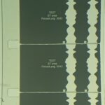
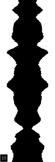
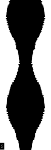
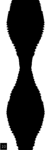
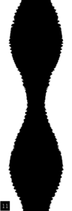
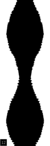
The video above shows each 1/24th of  a second as a frame of film in a 24p video. But we know that the solar cell/reader doesnt see it this way. These exported frames are a means of studying the kinds of shapes different sounds make ‘within’ the optical sound variable area technique (Matt has done V density, multihump, dual, uni-lateral, the lot).

So the sound comes first, I am working in sound, audio, recordings first and want to see how different sounds form different waves. The discrete output of frames to rephotograph onto filmstrips to make reproducible sound from film projectors is a by product of this process. If you did make Sts this way you end up with frame lines which produce a horrible 24hz buzz. You could machine down the corner of the super 16mm gate to connect the frames but we are in microns here, in an awkward area. Besides, there are thousands and thousands of frames. An exposed ST done on a proper sound camera like the one at WORM is effectively ONE picture. Yes. The optical sound strip down the side of a movie is ONE picture. Its one long exposure, like a ‘Bulb’ shot.

The purpose of the breakdown is to study the graphical properties of sound within the method of variable area optical recording.

Once a thourough study has been made, the next step is to devise experimental graphical forms, where THE GRAPHIC FORM comes first, ie its unknown (to a degree) what the sound will be like.

35mm film can have two different waveforms next to each other producing stereo, then later via matrix encoding, surround sound. This hasnt been implemented in Matts code, perhaps we can set chatGPT this task. Via the matrix decoding process

(https://en.wikipedia.org/wiki/Matrix_decoder

https://en.wikipedia.org/wiki/Matrix_decoder#Dolby_Stereo_and_Dolby_Surround_(matrix)_4:2: )

you can get L, C, R and mono Surround from 2 channels. With the bass crossed-over (filltered, not out but off) at 150hz into an FX channel you get your 4:1 dolby surround, the .1 being the bass, 1/10th part of the full audio spectrum. 5:1 just adds another surround channel, effectively making it SL and SR.


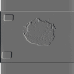
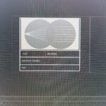
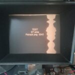
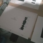
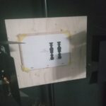
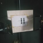
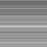
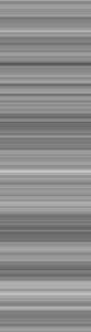
Above is a frame from a variable area sound output of pink noise. Even in a long video clip of this we get a random effect, where the image never seems to be the same. We could programme Processing to generate lines with different weights, thicknesses, spacings, densities from input like atmospheric or environmental and then photograph them on the ST area to see what they sound like. I recommend reading about pink noise on wiki, cos its totally amazing, weird and mysterious. It seems that everything is pink noise, music, brains, the universe, god!


Loading, please wait…
BACK TO TOP