Soon as I have finished some other things here in Rendlesham towers I’m going to get straight onto digitising the controls of the optical printer.
To do this I’ve broken down the functions, basic electrical control functions to 4 PAIRS.
This means there are 2 pairs of wires for the projector and 2 pairs for the camera.
Heres the first version of the logic.
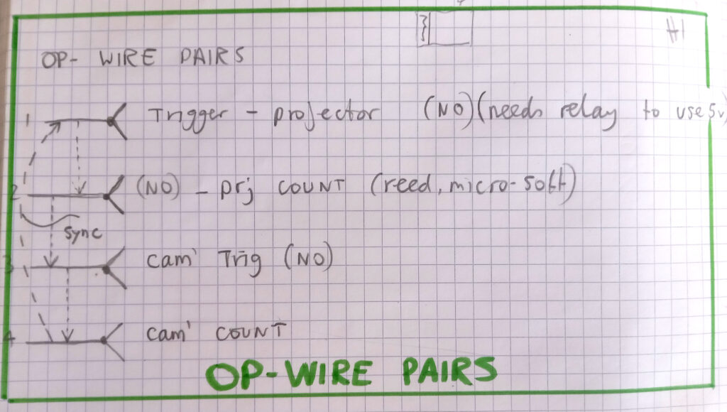
You can read the pairs on the left. The 1st pair is the switch used to trigger tje projector to load a new frame. This can be a momentary push button or a latching RUN button.
When it gets pressed it sets off a chain reaction, it effectively injects 120v into a relay, this engages a mechanical clutch, this rotates a shaft, this drives the printer mechanism to move 1 new frame in plus toother wheels, etc somewhere in there a micro-switch gets triggered which can be used to make a counter add a number and if its connected to the camera it acts as the PRIMARY device and a new frame will be fired on the camera. If this button is latched to RUN the whole thing will keep moving and you will get a 1 : 1 copy sequence going.
The 2nd pair is the projector count micro-switch.
The 3rd switch pair is the camera trigger. This can also be single frame or RUN. It produces the contact in the last pair for the camera count.
Now, if 2 is connected to 3 we get the sync as described above.
Now heres version 2.
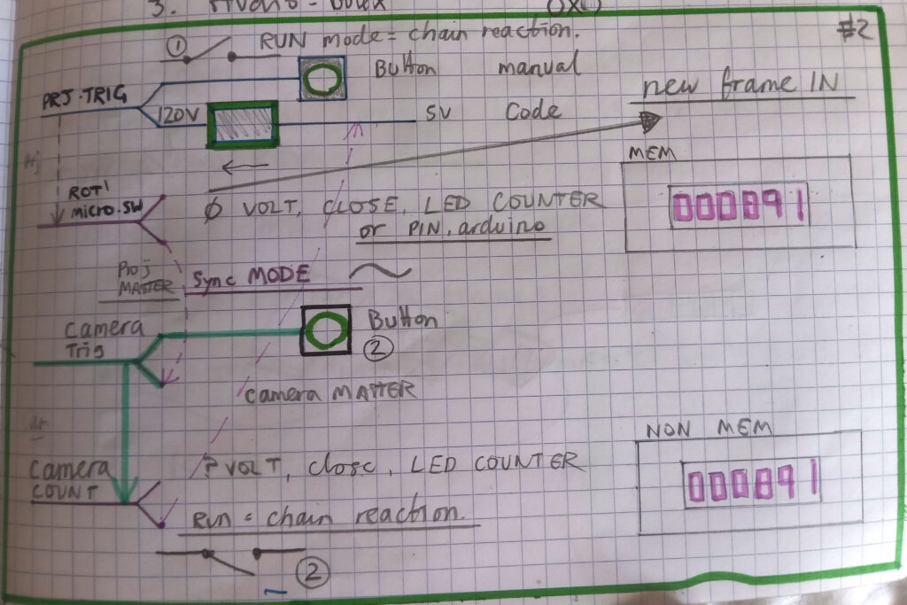
The same thing but with a bit of colour coding. Green for button controls and magenta for SECONDARY, controlled actions.
What is needed, to enhance counting and frame sequence creativity is something like an Arduino or Rpi to do all the counting and maths or rhythms or programming.
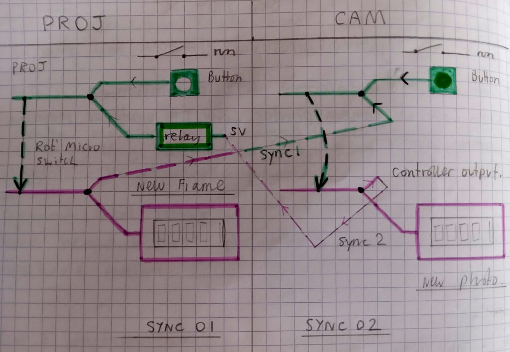
So, to help visualise this I’ve divided the switch pairs into PROJECTOR and CAMERA which stand lef tto right like they do on the actual machine. Its really clear from this now that what we need first is another sync mode where the CAMERA is PRIMARY and the PROJECTOR is SECONDARY.
Because the projector trigger button has 120v across it, I need to add a relay so that this pair can be fired from a digital device like Arduino. Once that is done there can be 2 sync modes.