This is hopefully the last time I post anything specifically about these motors and their applications. I thought, seeing as all the main functions are working that I’d draw up a plan for the whole system so that anyone can use it for themselves.
My application is simple. I want to drive ths camera with a motor that lets me control speed of rotation. 360 degree = 1 frame of film exposed. This frame is fired by a button like a shutter release.
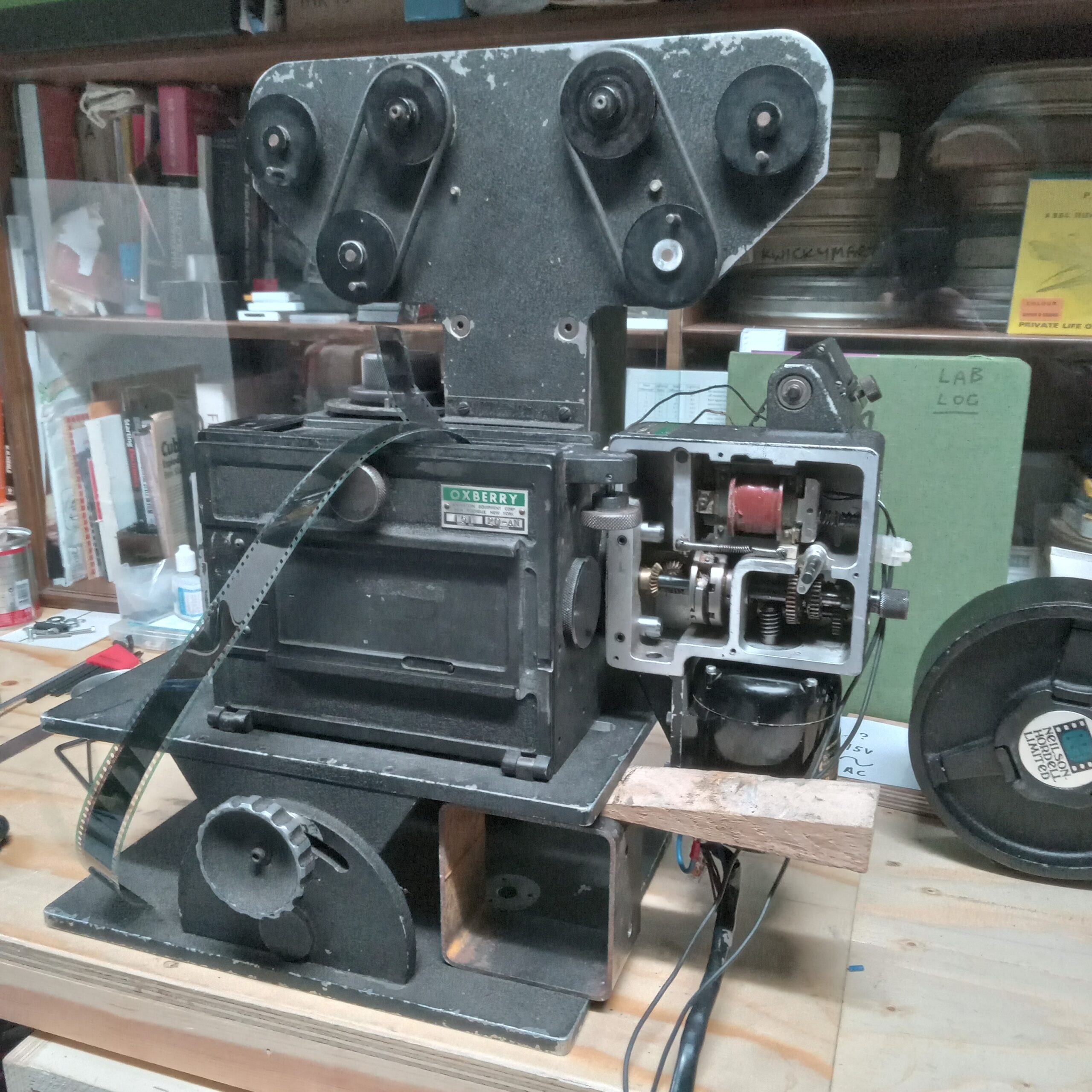
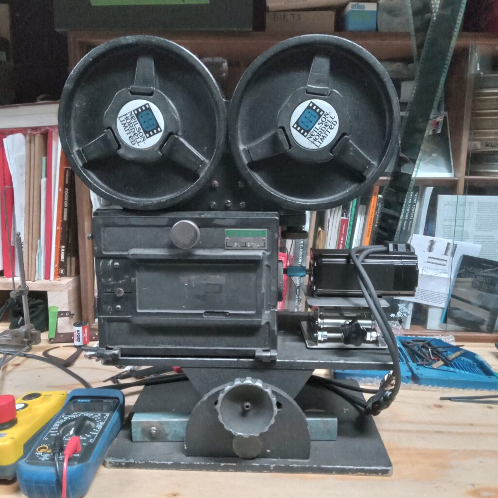
Heres the camera with a rival motor system, an old Oxberry printer drive. It actually hooks up and works. It runs of 120v and has 2 speeds. The solenoid fires at 35v odd and slips a clutch which then engages the camera shaft and fires off a frame of film. However on the negative side, the motor is noisy and has a loose bearing so it could produce quite a lot of vibration which is undesirable in animation. It is bomb proof but I am super curious about closed loop stepper motors and what they can do.
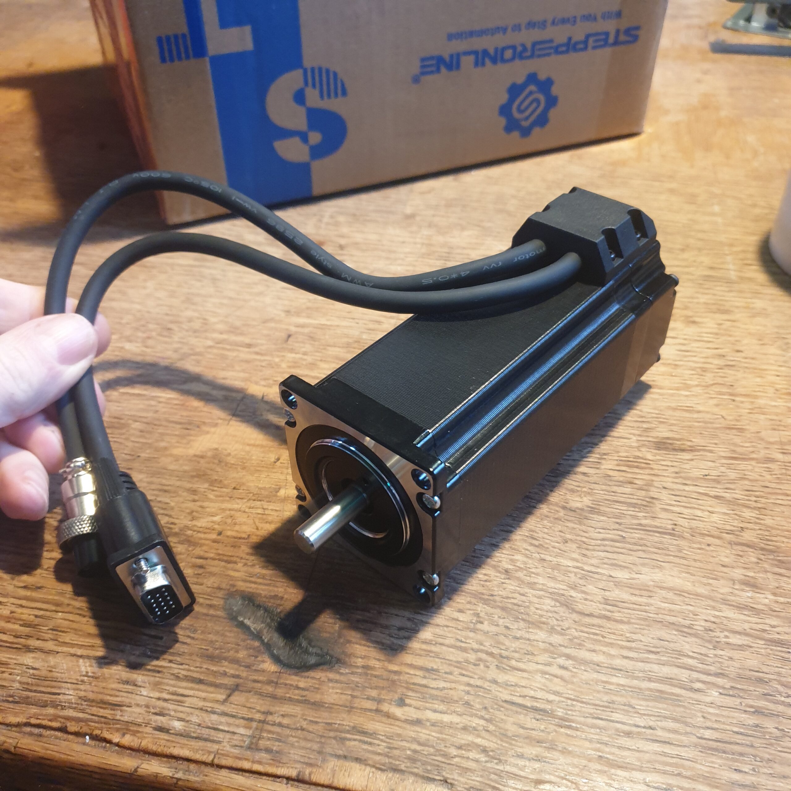
Heres the stepper motor. I wanted something beefy that had enough heft to drive the camera and not ever struggle. Technically if you match the Nm torque needed to to turn the camera over with matched stepper motor you end up with a small motor. I dont trust that such a small motor can do the job. This motor’s holding torque and other specs are plenty for this job. Closed Loop motors have an inbuilt encoder with connections that are made to the driver. This means that when powered and when it is resting at a signal pulse position it will not deviate from this position and if you try and turn it away, which takes some force, it will spring back to where it should be. If you disconnect the power you can freely rotate the motor which will be required when threading or lacing the camera. BUT, once you have done this, you need to position it back in a ‘true’ position or else when powered up again it will make a tiny snap to the nearest resting place. This is tweaked by programming the arduino which we will see later on, but basically you can make it step tiny amounts 1 at a time and thus you can align it this way.
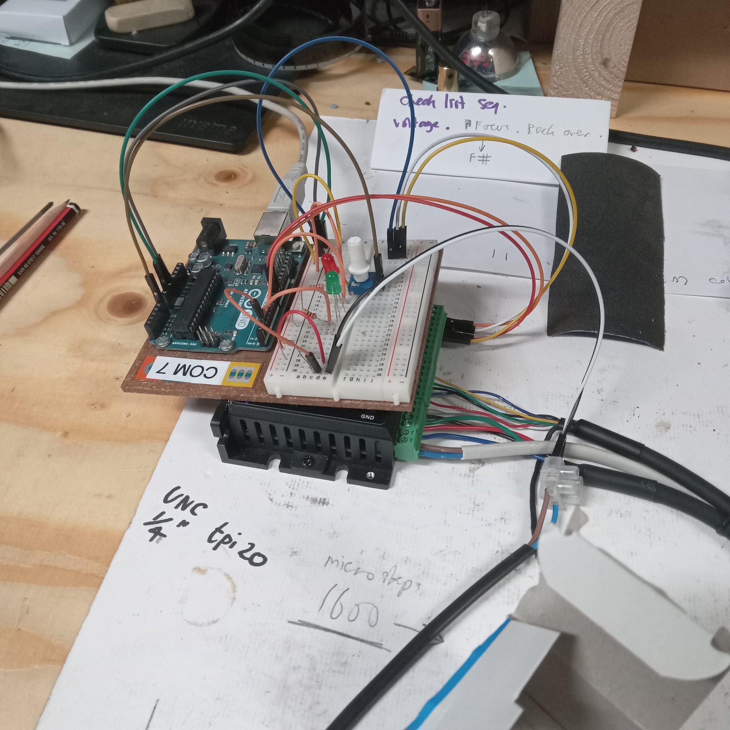
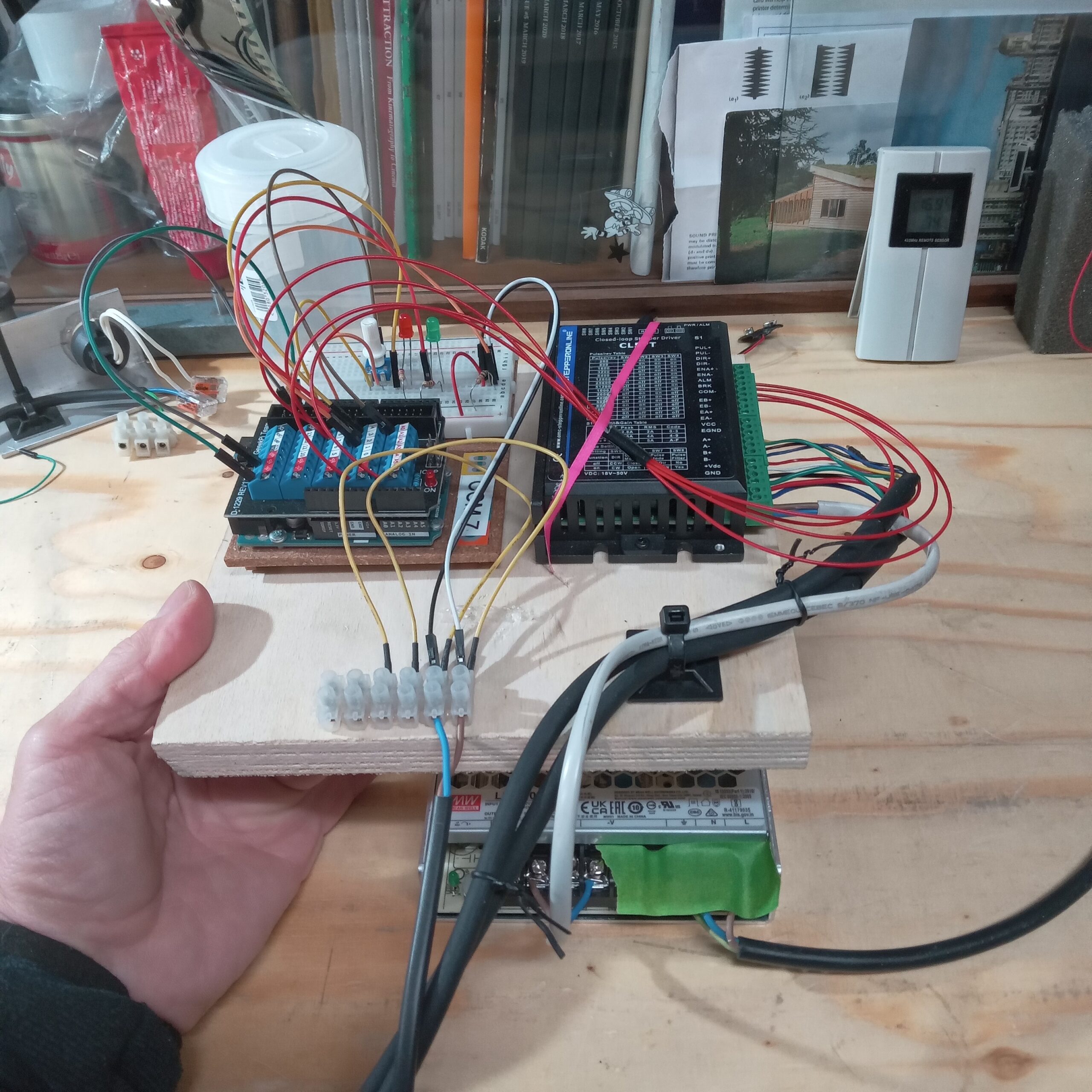
Heres the Arduino UNO sitting on the driver which is a CL57T by stepperonline. On the right are control signal wires from the UNO. Multi coloured encoder wires from the motor and the brwn/blue 36VDC from the PSU.
 |
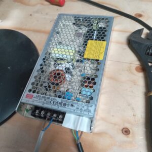 |
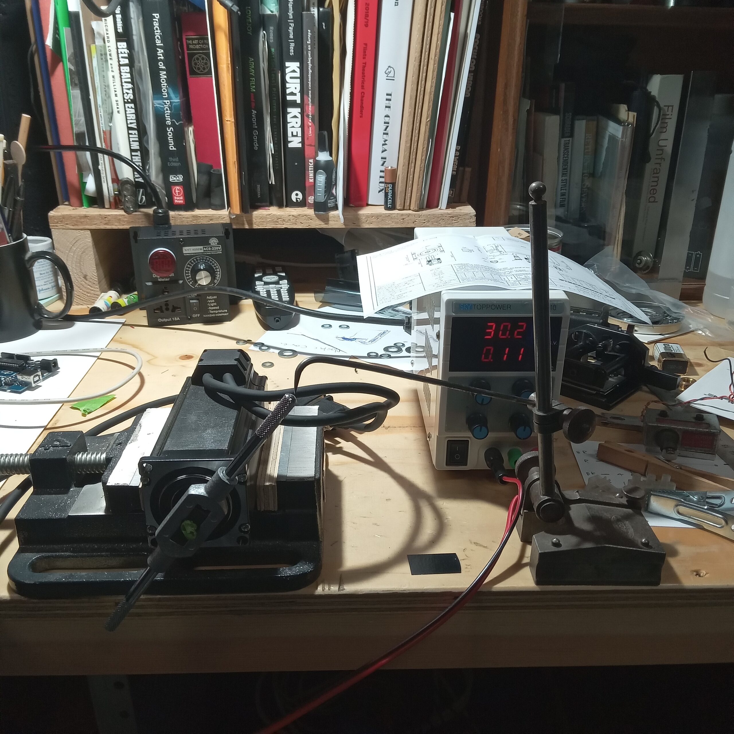
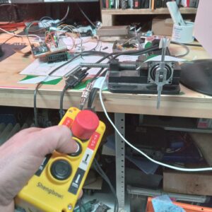
Heres the motor in a vice to test and then the motor offered up to the camera with temporary mechnical coupling. Below is the PSU.
Below is the button unit I bought that has a few options that I can exploit. The red STOP button will interupt the 36VDC so that I can turn or thread the camera manually which is required for oxberry gates. The white button currently fires a frame. The black button, well, what could the black button do? On the UNO board (I will post a proper schematic soon as) there is a green LED, a red LED and a pot. The pot controls the speed of rotation. The greed LED lights when the camera has stopped. The red lights when the exposure is happening. The button wires also come into the board. The whole circuit is EXTREMLEY simple. Below is a video of the button firing a frame
For the observant amongst you, you’ll notice that the button is pressed twice! This is me trying to programme a BULB setting by putting only 50% or half of the correct turns into the Arduino sketch to get a full rotation. This motor has 200 steps per revolution set to 8 microsteps which means that 1600 steps = 360 degree = 1 frame. However if you type in 800 then the motor only turns half a rotation meaning the shutter is OPEN. Then when you press the button again it turns half again thus completing a full turn. On Oxberry movements careful attention must be paid to the pin registration phase of the cycle so that the film is being held correctly. The great thing about Arduino is you can make these changes, upload and have different functions in literally seconds. There is no need to design and plan and write some great big application that does all the things you think you will need. Below is a video showing the motor coupled and me making a speed change whilst listening to the Titanic series of podcasts by the Rest Is History blokes. What Im telling myself here is that Ive turned the pot down. When the pot is turned down the values it feeds the Arduino effect the way the motor is driven. I’ll post the code below in full but basically the pot gives a range which is usable from slowish to fastish. We dont need to be dealing with exact shutter speeds yet but we will come to that at some point. Faster speeds are unwise to test with the temporary coupling because the motor will easily slip out.
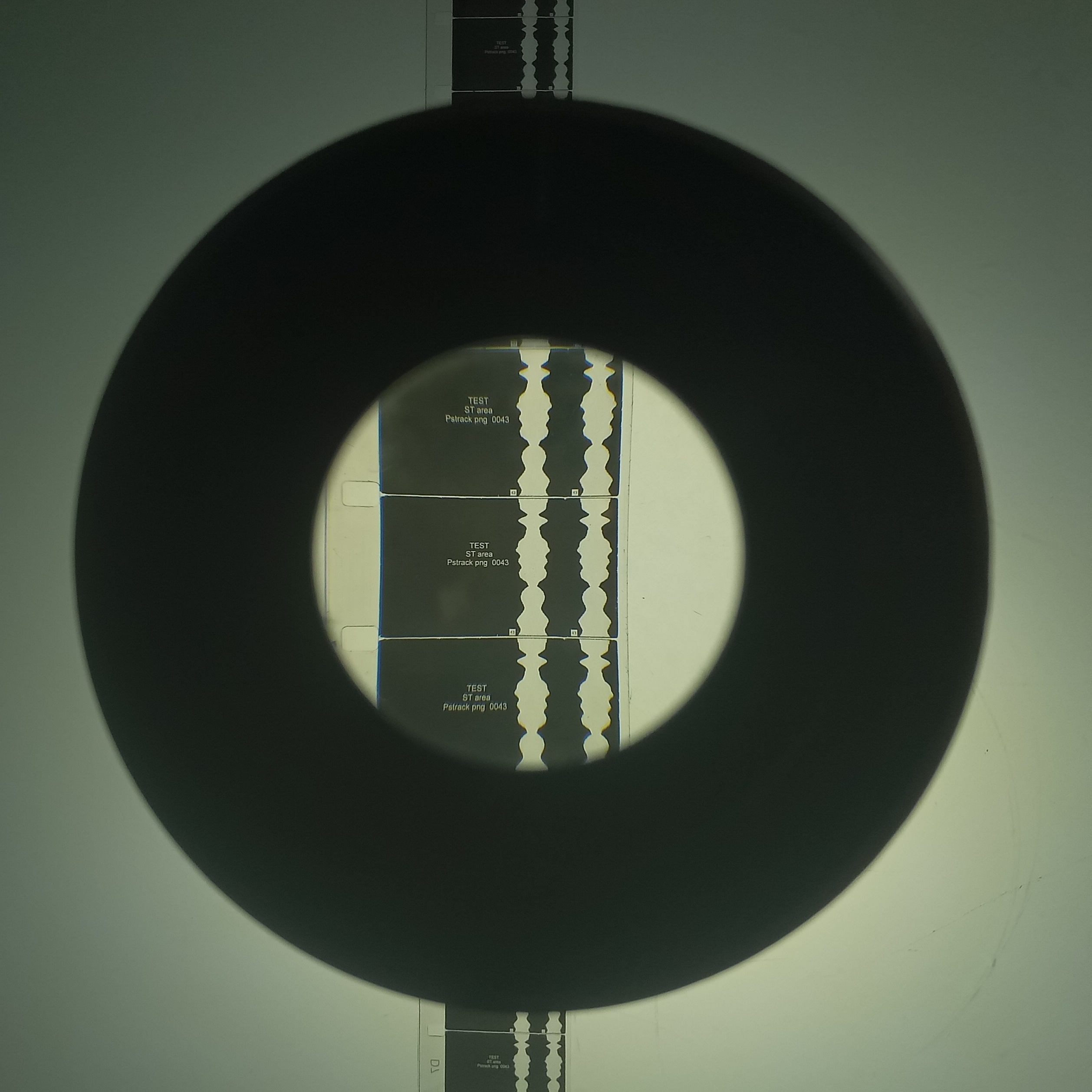
The motor is driven by using micro-second delays between pulses of 5v effectively to the driver. So you can very accurately make timed rotations in milliseconds. But, the shutter is not just an open disc. It itself can be adjusted and its OPEN angle is 170 degrees. So for a rotation of any given value in time, only some of this will be an exposure. Ive been simply using high speed video footage to measure the shutter speeds on the other Oxberry. But as that is usually used for printing its not critical. This unit I plan to use as a camera so will need to dive into absolute shutter speed vlaues at some point.
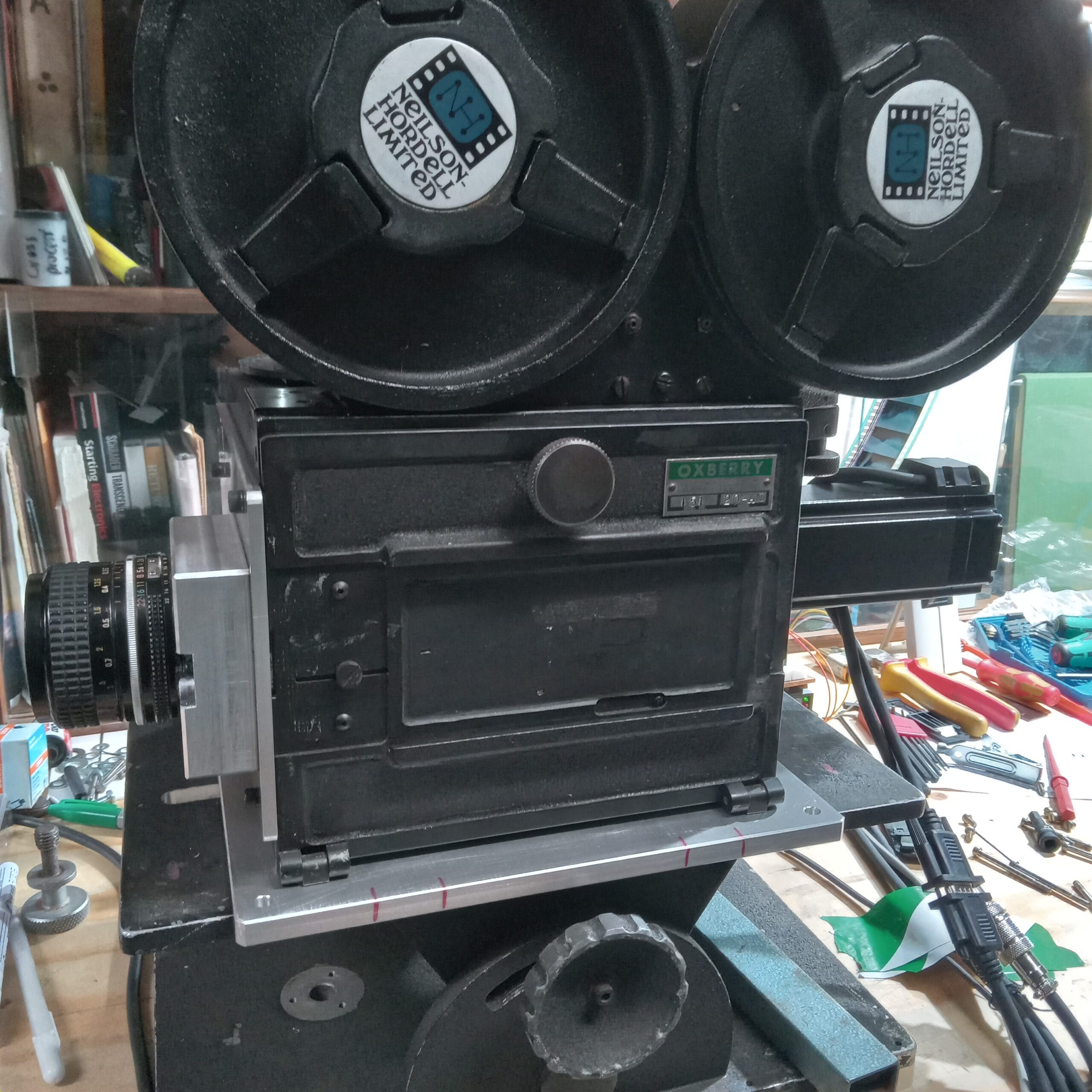
Heres the completed camera. A word on shutter speeds.
We can ascertain from the arduino programming how long a 360 rotation is.
We then divide this number by 360 to get time per degree. Then multiply by 170 (or another shutter angle) to get the exposure speed.
I will also do some hi-speed video as this gives an absolute visual record of shutter speeds.
For all use fomr here on, it might be useful to do the maths to create common sutter speed fraction values, 1/2, 1/4, 1/8 as well as 15th, 30th, 60th, etc.
Heres the electronics. Theres tons that can be added like speed selector buttons, second switches for DIR, etc. But for now I like the fact the function is baked into the
code so cant be changed easily.