(still editing and formatting this post/page)
Early on in the formation of the DIY film lab scene there was a meeting in Hamburg or possibly Hannover (sector 16) or somewhere else where I saw mentioned the idea of converting steenbecks or other flat bed edting tables into contact printers. Esther also mentioned this at WORM and a howto appears in their DIY booklet. So I have always wanted to do this and now I have and it works very, very well I dont feel the need to get a contact printer. Also as it doubles up the use of one machine into two, its very economical.
The main thing is that everything is there to allow this BUT somekind of device or part needs to be built that creates a small slit which the light passes through as films which are bi-packed travel pass. We know from how ‘proper’ contact printers are designed that this slit is crucial in producing a ‘blade’ of light that exposes the film. A wider more diffuse beam will cover too big an area and contain variations within it which will make for a messy transfer.
Here is a fullish documentation of the steenbeck contact print mod that I have been using.
This adaption of a steenbeck is completely non-destructive and the machine can happily be returned to its normal function in a matter of seconds.
To carry out this adaption you will need the following:
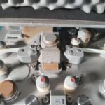
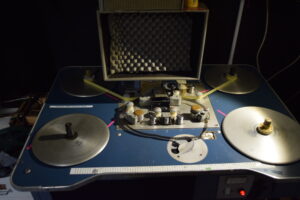
1. Somekind of camera/printer magazine to house the RAW stock and allow it to feed out smoothly. I am using a Mitchell style magazine which is clamped onto the left side of the machine with enough packing to make it the same level as film normally loaded onto the viewer. This magazine could just be a light proof box, pizza box, anything that protects the film from the light which is useful for lacing up.
2. A slit / gate type thing. You could try printing without this, but the bulb in a steenbeck is bright enough to totally over-expose the film (for eg Kodak 3303 or ORWO PF2) and you will need someway of placing ND filters in the light path. More on the slit later.
3. Usual stuff to put exposed film into bag/tin to take to darkroom.
4. Some thick foam, blackout material.
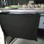
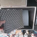
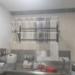
The first things to do are block any light leaks. I use a black casement material but cinefoil or thick card will do. Turn the machine on in the pitch black and look out for leaks. With the viewer light on a very obvious leak is the screen itself. Make up a piece of foam (from camera case) that fits tightly inside the viewing hood. In my experience so far the red power button does not fog the film
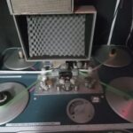
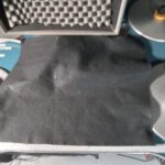
Next, the magazine is seen here clamped in position. It can be loaded with 400ft of RAW stock and left in this postion all the time as it does not interfere with normal operation. That clamp is useful for other things so will make a bracket for this at some point.

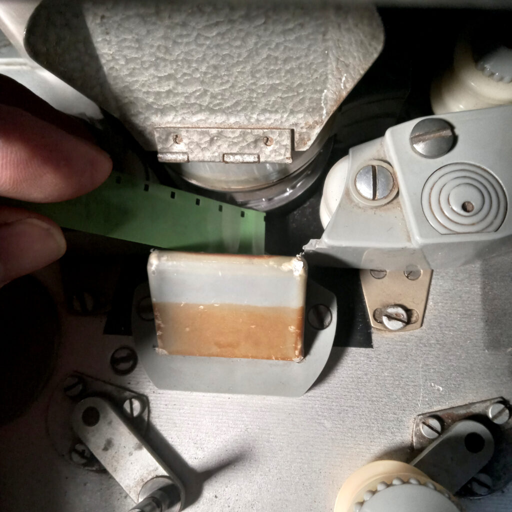
You can perform these steps in room light and only the section of RAW stock you handle will be fogged. You first lace the RAW stock into the steenbeck head making sure to purchase the sprockets. You can wind a bit forwards onto a T-core or spool. You could also do this with red safe light on to save film but it can be a bit tricky to get both the films into the gate area.
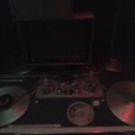
Then you lace up the negative or material you are printing using the lower platter seen above as green leader. Re-open the gate guide rollers and slide the neg INFRONT making sure to feel the teeth purchase on both films. I always wind a bit forwards here as the noise it makes is a good indicator of correct lacing.
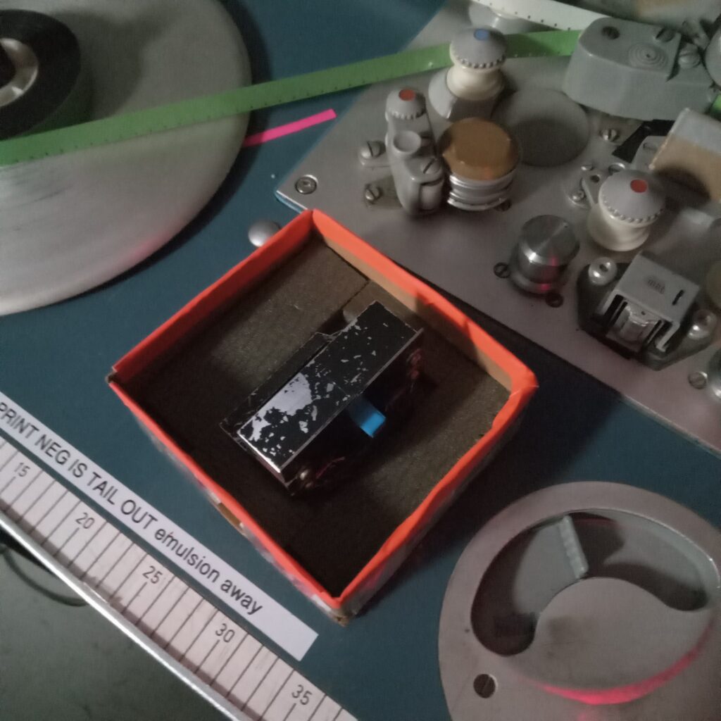
The usual convention for contact printing is emulsion to emulsion. However, the neg or OG (original) film you are copying is actually TAIL OUT in this set-up as it is impossible to load it HEAD OUT with emulsion facing away and sprockets DOWN (steenbeck convention).
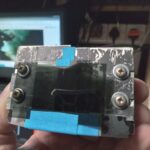
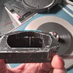
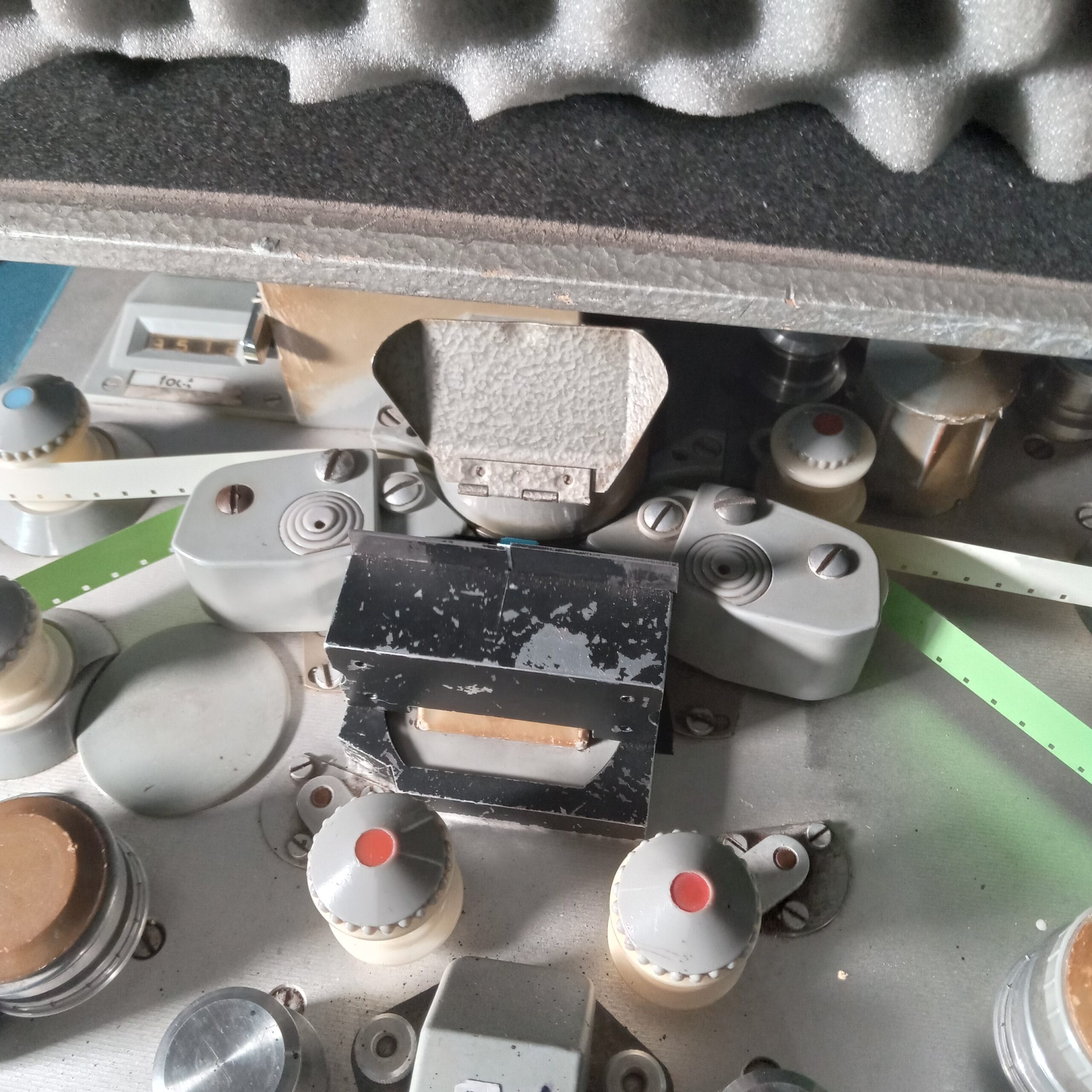
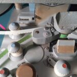
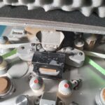
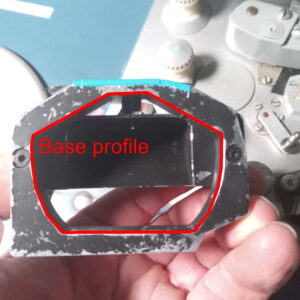
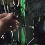
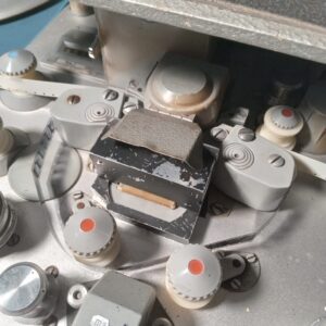
Now both films are laced you can place the gate/slit into its position. A close up of the gate shows that mine has been made to fit exactly the profile of the mount that holds the prism. People will have to explore their own ways of doing this. 3D printing perhaps
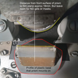
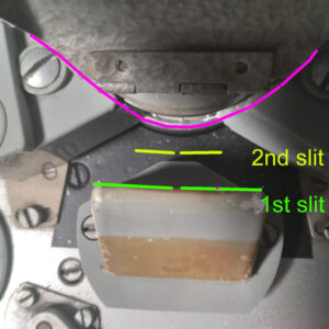
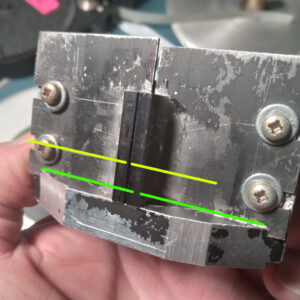
My 1st slit (green) was right next to the prism, seen here built from 2 metal curtains which are machine screwed tight to the holder. This idea was the thought that different slit widths could be tried. But as this slit is too far away it creates dispersed shadows either side of a brighter slit. No good. Adding another slit (yellow) only about 10mm was done by adding 2 rectangular metal bars seen here glued onto the curtains.
 What you want to achieve is a slit about 1mm wide, as absolutely parallel as you can, that is as near to the film plane as possible but with enough room to be able to tape ND gel onto the front. 3D printing might work, etc. The quality of a contact print depends on the nature of the OG and you will almost surely need to make several tests until you get the ND value right.
When gate/slit is in place I cover the whole gate area with another black cloth just for superstitious reasons. Then you can enter darkroom state with safety light of correct type for the RAW film you are using. You can run steenbeck forwards now and when ready turn on the lamp button on controls which I have marked with tape so as not to hit the sound amp/exciter power which for some reason on my steenbeck is before the viewer light??? As the machine runs you can see light emanating slightly from the left of the gate, when ready you switch the light off and let it run a bit to leave a bit of leader.
Now the scissors you have hanging around your neck or by the machine can be employed to cut the film, I cut over by magazine and run last bit of film off. Then load into bag/tin and take to the processing department for develpment.
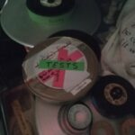
If I had a quid for every time the gate/slit device was accidentally knocked onto the floor I’d have about 5 quid now. So I made a little padded box to preserve its special and fragile nature.
NOTES.
LOOPS.
An obvious thing you can try is making up LOOPS which will print over and over again. This will put your splicing skills to the test.
MASKS.
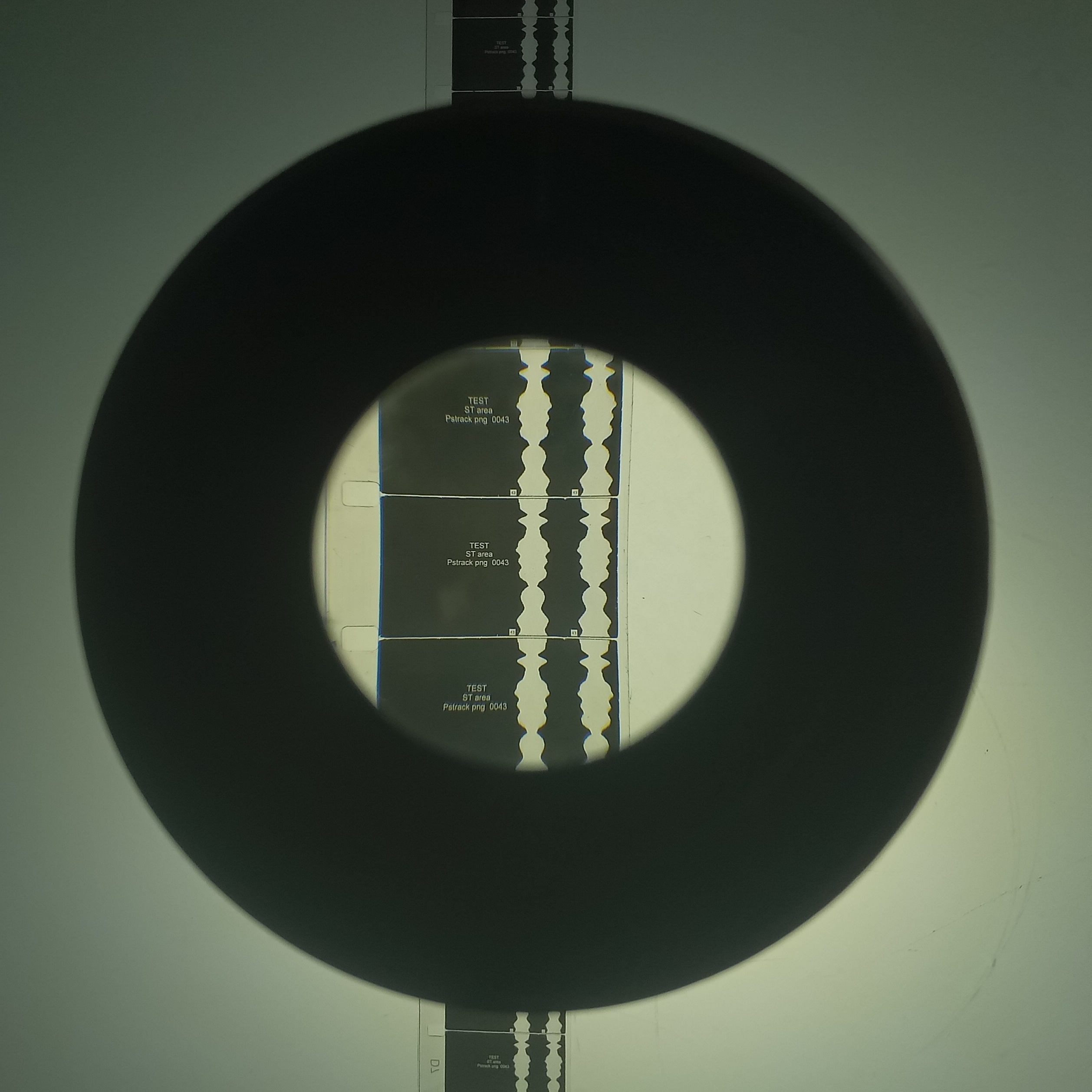
You can make masks out of black tape and place across the slit so for instance printing onto the image area only and holding out the soundtrack area. Then rewinding the film, loading a soung neg, reversing the mask and printing to the sound track area.
RESULTS.
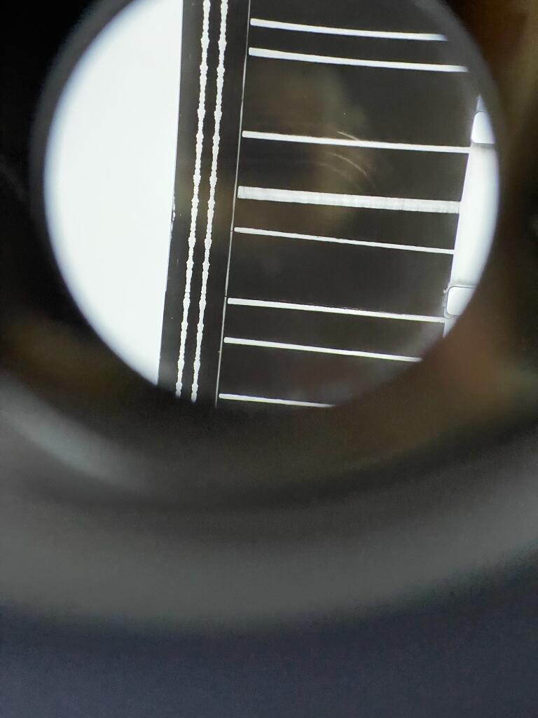
The results are extremely good I’d say. A KEY factor is the accuracy of the parallel-ness of the slit. If the slit is for instance tapered, which you could do on purpose, then the exposure will not be even across the frame. Tiny imperfections in the edges of the slit and thus the parallel will show up. In copies so far for instance I can detect no difference between an original soundtrack and a new copy made this way. IMHO so far a slit of 1mm with no ND way overexposes the film. This is good, you might want to do this. Well exposed 3378 currently prints at ND4, and well exposed 7222 around ND1.5. But with a 1mm slit, which is easy to set with feeler gauge or such thing, you have plenty of headroom to stop down with ND gel. Its great, it works, DO IT YOURSELFS. Happy to answer questions or help you make your own conversion.
One more thing, as it is operated sitting down as you do when editing, its really easy and fun to work. I do things like count to 90 to get 50ft lengths for my lomos. A digital footage counter would be nice!! I’d even go so far to say I enjoy this printing more than optical printing which is like plate spinning 13 antique ming vases whilst balancing on a football with one eye shut and wearing a rucksack filled with 9 kittens whilst simultaneously brushing your teeth and typing the complete works of shakespeare with a mechanical typewriter that is strapped to a goat that is dancing on a hot plate with a firework tied to its body which have the fuses lit and are about to go off!
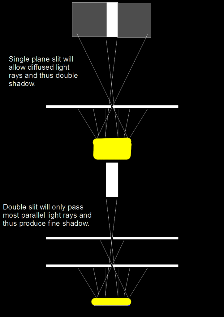
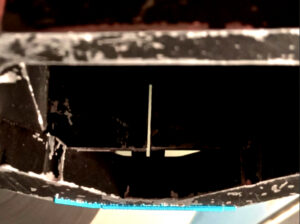
Heres a bad illustration of the optics that you have to think about to get as fine and sharp a slit as you can. Also, the double band of light is a function of how close the slit is to the film plane. This area on most steenbecks is about XXXX. So my adaptation is based on the fact that the metal holder and curtain arrangement was made before learning about the problems with shadows. So design something that gets close to the film plane but still allows ND gel to be taped infront and/or black tape. Experiment with a ‘corridoor’ rather than a slit/s as this is the same thing.
OTHER FACTORS.
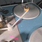
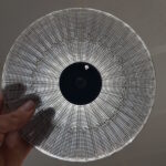
This method uses the steenbeck lamp and optics. They shine up from underneath, bounce off a small front surface mirror, pass through a 45 degree prism, pass through the film, then a multi-facet ground rotating prism, then a lens, then more and more mirrors until finally arriving at the screen. Crazy, like a metaphor for lifes journey! Of course as a contact printer the light is STOPPED at the film plane so the only factors in play are the lamp adjustment and the cleaniness and postion of the prism and mirror. The prism is easy to get to to clean but the mirror sits in a tube and is held in place by a spring. It can come out of position as you try and clean it and is a bit tricky to get back into what feels like a correct position.
Motor speed. I’ve had some speed playback issues with this machine. Sometimes its wow and flutter are dreadful. Ive got some spare cards from Lew (thanks Lew and Matt Davies). I’ve looked into the sync-comparator circuits and given up trying to understand. Then the next day it will play fine. Does this tiny variation in speed effect the exposure on a contact print? I guess we can look out for a kind of ‘flickering’ across frames and match it to this error. I guess it is like anyone and has good and bad days.
TO DO.
Devise some way to synchronise sound and picture. As neg and raw are locked together in the gate this could be a case of marking the RAW from a sync mark on the neg, then after rewinding and making the necessary 26 frame drift or whatever it is, placing a sound neg ‘1khz POP’ in the right place.