Stepper Motor camera drive #01

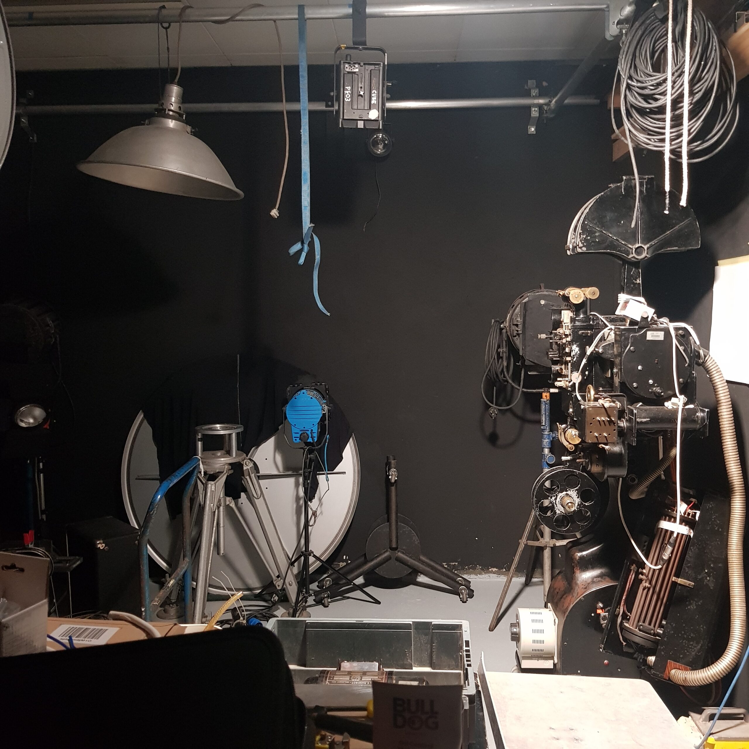
Most of the cameras I use (and projectors for that matter) are driven by a motor where one full turn, or 360 degrees equals one frame of film (they are all optical printer or animation cameras).

There obviously needs to be position accuracy because the camera needs to be closed when the motor has spun 360 degrees, made its exposure and comes to rest, ready for next frame.

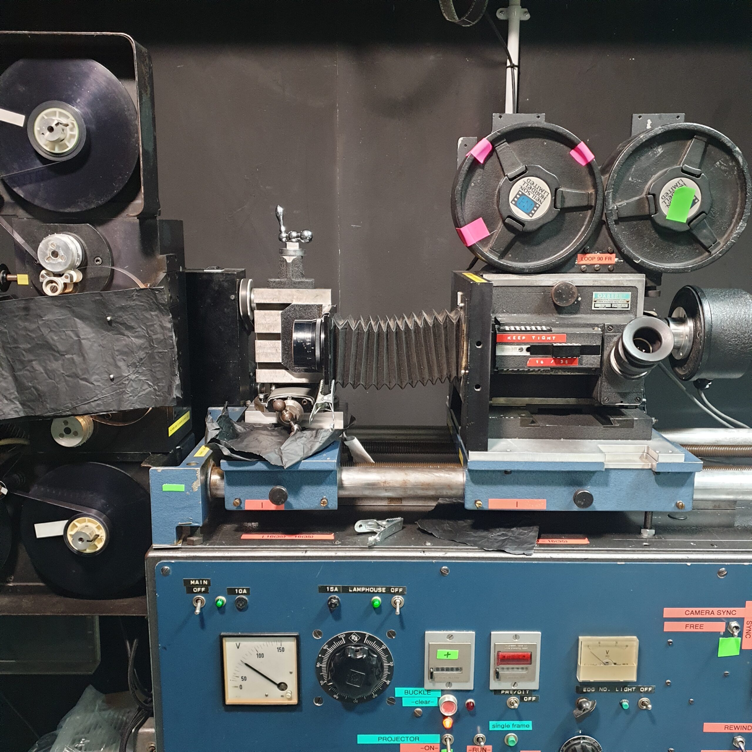
The way this is achieved varies from camera to camera. On the Oxberry, the motor is an expensive ‘pancake’ style printed armature motor. Its spins very smoothly, has zero ‘cogging’ and other features. Its position is known to itself because of an optical disc that stops after each rotation. This is handy BUT what if I want super long exposures. And, to replace this motor is cost prohibitive.

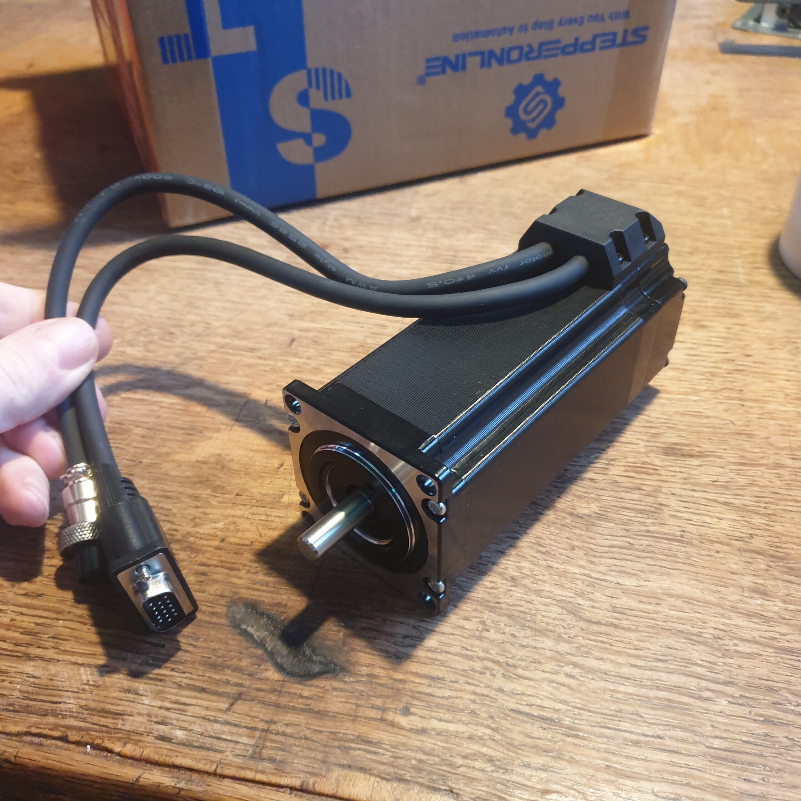
Enter Closed Loop stepper motors.
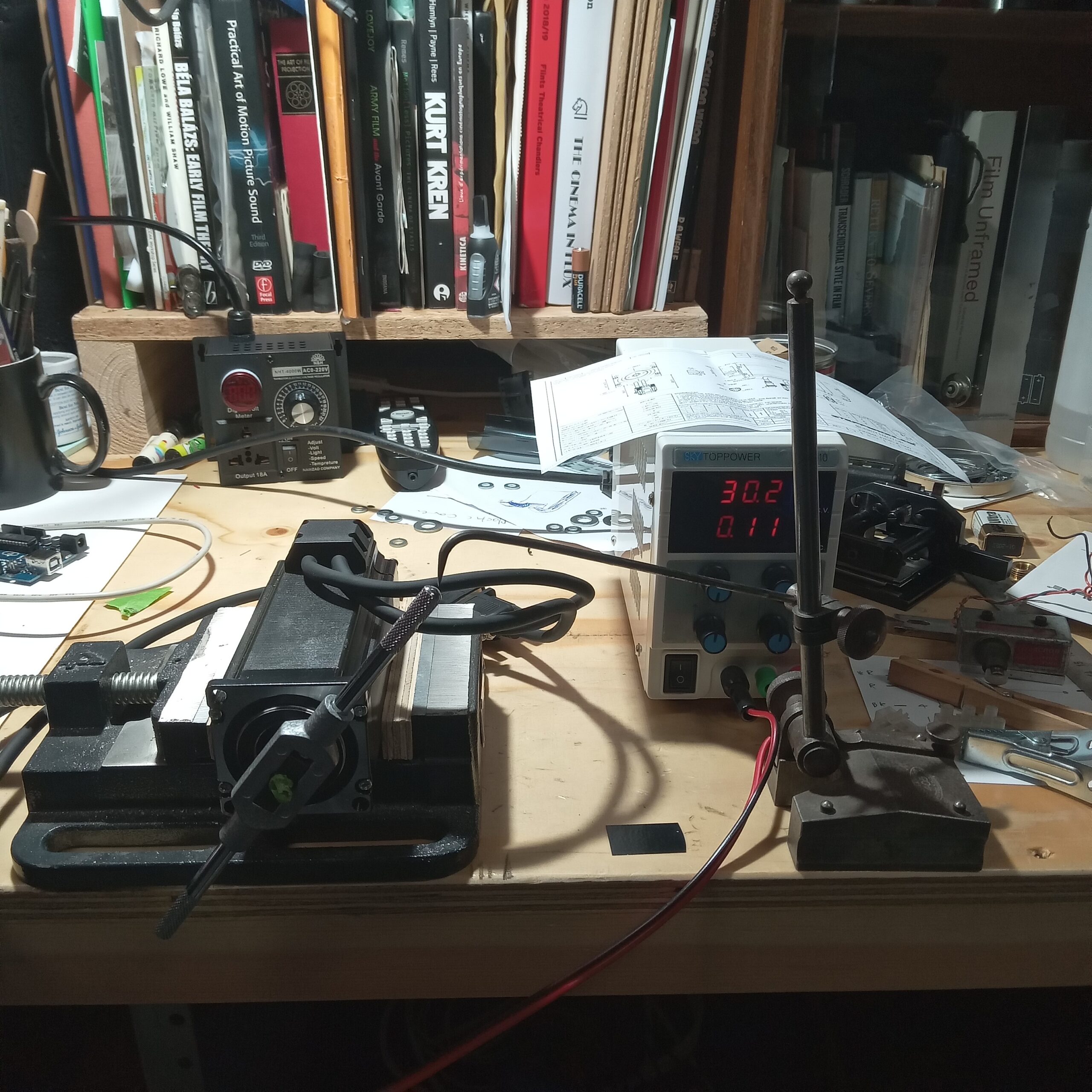


These systems have really improved in recent years so now for less than £100 you can get the motor, the driver and the PSU. To operate the motor, ie to make it spin, a microcontroller is used such as Arduino or Raspberry PI. I am using an Arduino.
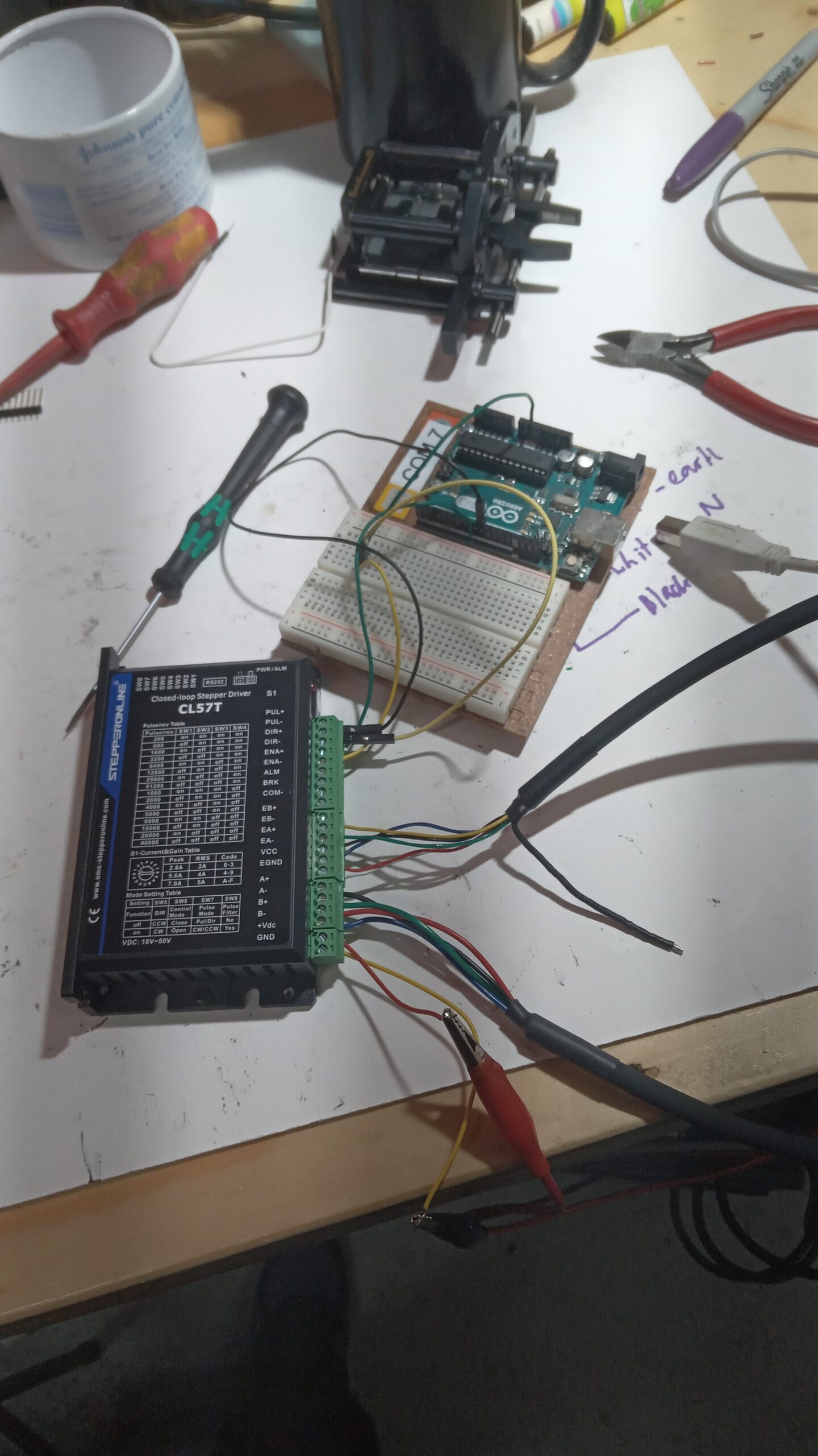
The functions which the motor will be programmed to perform can go way beyond that possible with the motor system on the optical printer. However, the printer can extend its functions by also being controlled by an Arduino and I am working on this aswell.

For this experimental animation / plate / studio camera I need a way to control exposures and position as well as other possible inputs like the postion of objects being filmed.

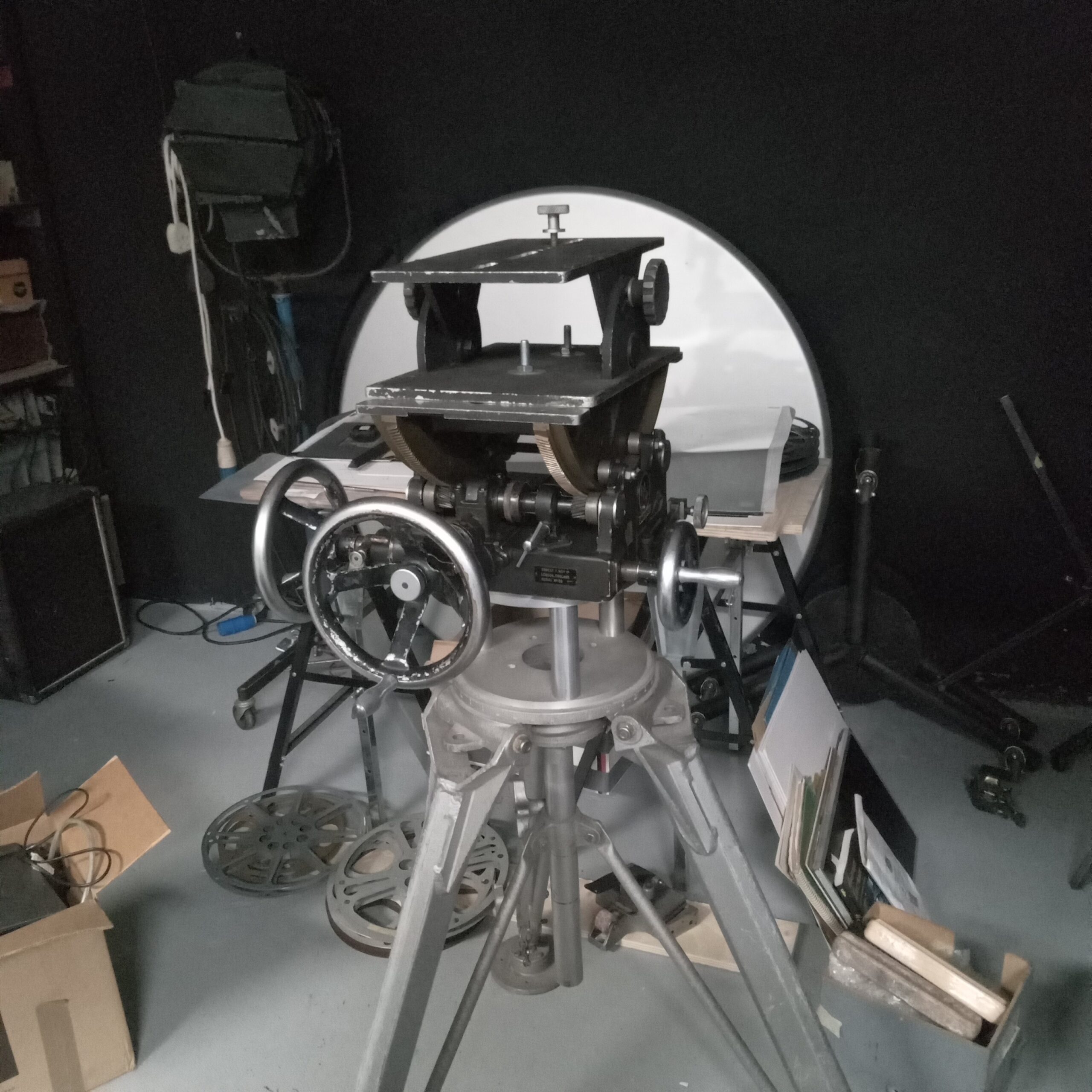
I’ve dug out the beast and next need to design mounts that place the camera at the nodal points. These heavy geared heads were really useful in the old days when your cameras was also heavy. To machine something like this now is cost prohibitive but thanks to digital ‘progress’, you can buy them if you are lucky enough to see one for sale. I dont like the design of the top angle plate, held only by bolt tension. Decent heads have a pivoting shoe design that has mechanical rigidity. If a heavy camera slips on these tensions it could crush your hand or a finger.
Back to the Arduino programming. It’s hard. Thats because I’m not a programmer or coder and so I have had to start at the beginning with getting an LED to blink. Some deme code to make the motor run has kept me busy as you can see below.

Quick wish list function table……………..

MODE FUNCTIONS SUB menu
Inching manual turning to thread/unthread film motor psu-
Zeroing Bring shutter into correct position count?
Single Frame Push button single frame / manual / speed options (speeds)
‘B’ Push button shutter open/close / manual  
‘B timer’ Push button shutter open/close / programmed time (Time)
Reverse Prepare for reverse / shooting / frame find (speeds)
Rewind Rewind to set frame Frame #
Single Frame / SP Single frame exposure on special event / input (speeds)
TimeLap Programmed single frames and intervals (Speed & Time)
Cont’ Run Set frames, speed, running 12fps MAX (???)  
     

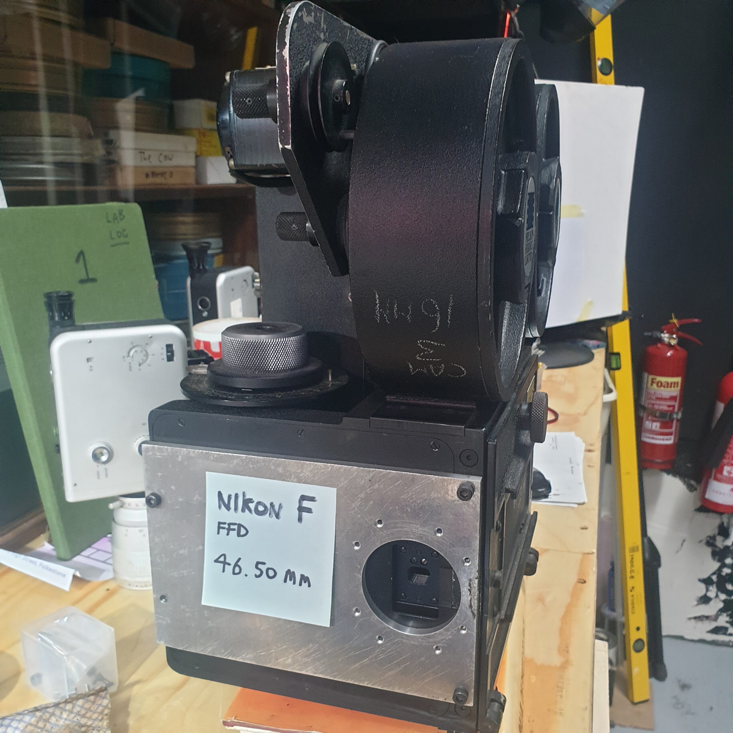
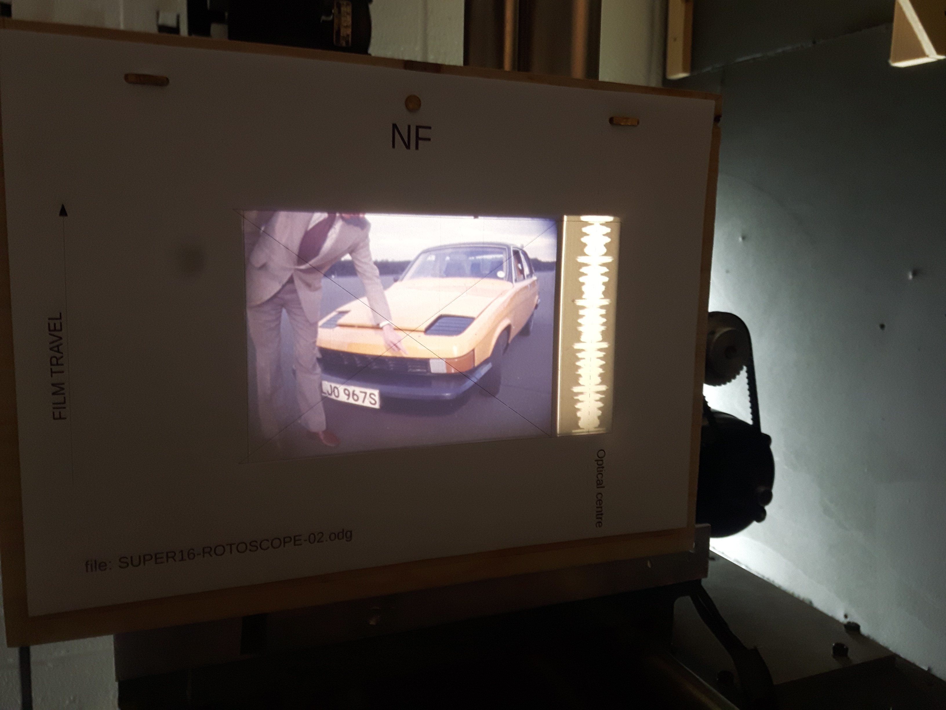
Then, after NIkon F mount plate is done we can start Rotoscoping to our hearts content.

 

Getting camera prepped………

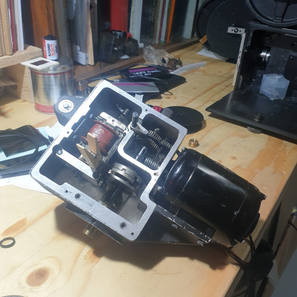
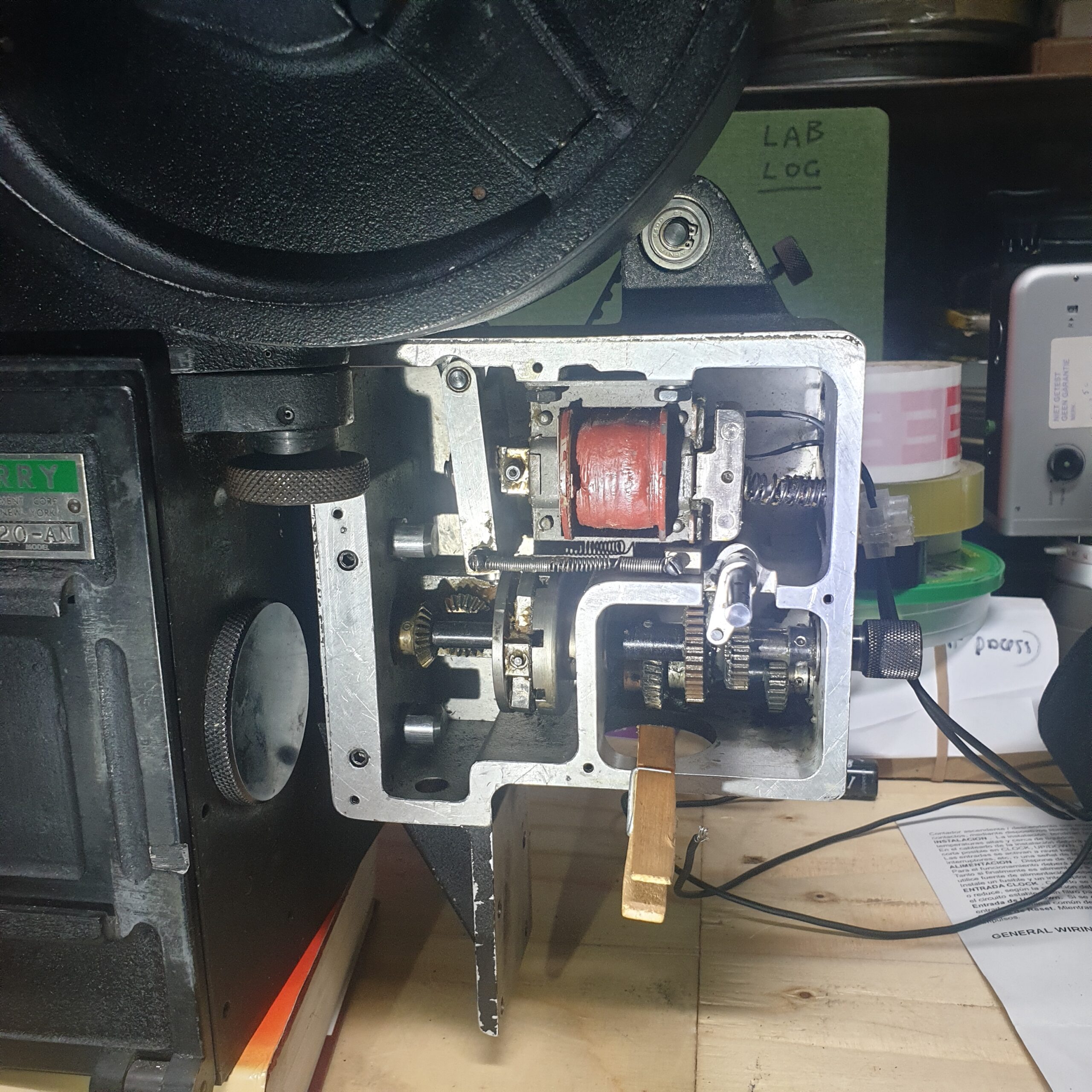
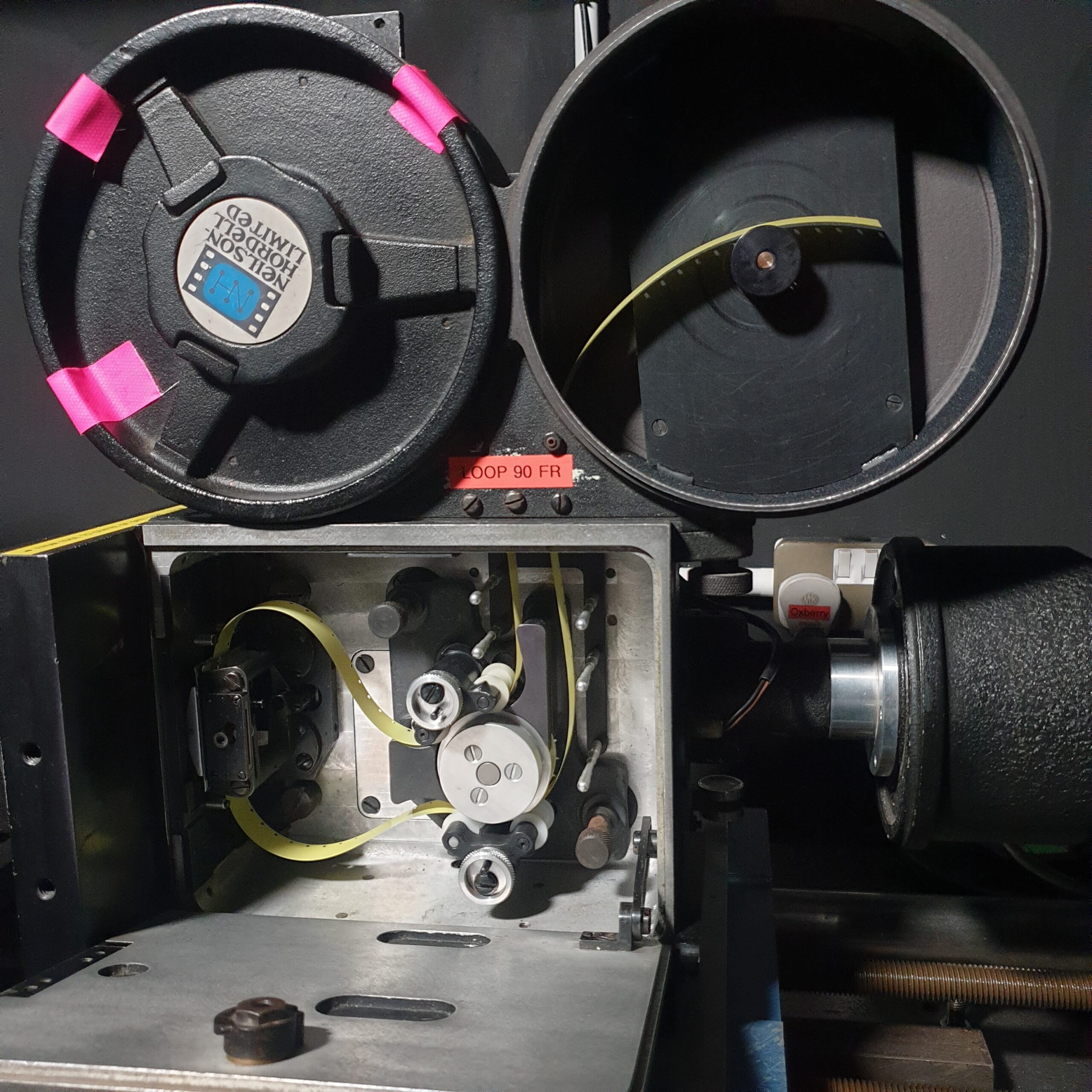
To get this camera working I’ve managed to hook up another Oxberry part, actually a 2 speed projector drive, seen below.

The motor runs on 115v ac and the solenoid fires at around 36vdc. When the solenoid fires it allows a clutch plate to slip thus engaging with the driven gear shaft and momentarily (ie 1 frame) turning the camera drive shaft which equals 360 degrees and thus 1 frame of film.

Although this will ‘work’ and allow exposures to be made it has limitations that that conflict with sonme of my planned uses, specifically long exposures of several seconds and sometime minutes. To afford these functions I have invested in a closed loop stepper motor.

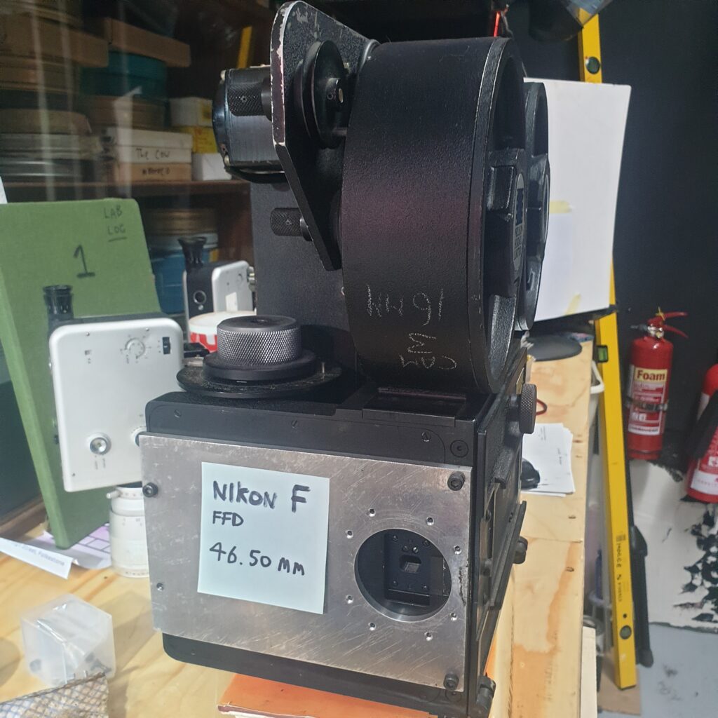
After all this the last thing will be to get the Nikon F mount at the correct distance from the film plane.

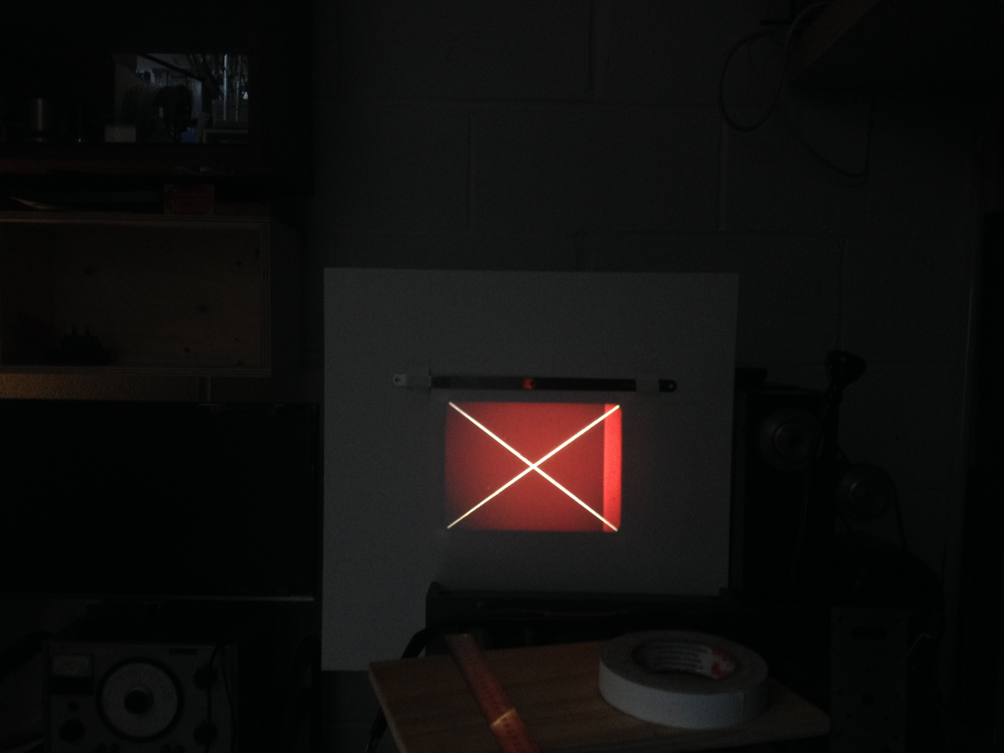
I have already tested this distance to check lens function by rotoscoping and all is well. This camera body has a boresight opening which may allow some kind of framing as long as the sprocket drive is removed.

However, Im not so obsessed with this function as I Like the idea of framing by projecting a small piece of clear film and seeing whats in the frame and where it is. It will be a heavy thing when finished hence the geared head I bought a while back. My planned uses Im gonna keep under wraps for now but just to say it will be a kind of studio / plate / process / animation camera for both 16mm and 35mm. Interestingly the camera body has an 8 perf opening by the gate so, using a vistavision shuttle one could expose portrait format 8 perf film!


Sensitometry / Densitometry Fun

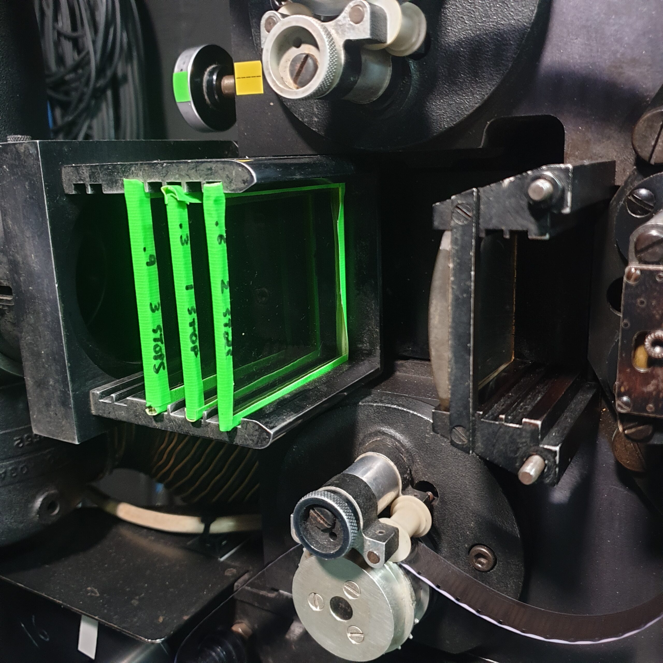
Table for ND filter set. Made up from only 3 gels. Half stop gels are sold by LEE. Can do 21 stop wedge strips then.

filter #stop# gels in
frame
# gels in
frame
# gels in
frame
Optical
Density
%
Trans’
ND0.3 ND0.6 ND0.9
1110.350
2210.620
3310.912.5
44111.26.25
55111.53.12
661111.81.56
77212.10.78
88122.40.39
9932.70.19
1010133.00.09
1111133.30.04
121243.6
1313143.9
1414144.2
15151144.5
1616244.8
# gels in
frame
# gels in
frame
# gels in
frame

Shutter speeds /deimos control. Need to double check by shooting some hi-speed video on phone.

shutter
angle
Deimos setting 1Deimos setting 2Deimos setting 3
millisecs640340250
fraction (using above)16/2517/506/25
170º1/2+ of a sec1/4+ of a sec1/5th of a sec
85º
42.5º
21.25º
frames open/HS
240fps
140 frames
(7/12ths. 1/2+ /sec)
66 frames
(1/4+ /sec)
48 frames
(1/5th /sec)

Owing to the hybrid and vernancular nature of my printer, the camera speeds are not set the same as on a proper Oxberry. The Oxberry printer head has 4 speeds set by a gearbox effectively. However, the faster speeds, say 4/second will cause problems when used with Deimos speed 1. Thats because that camera speed is only 1/2 a second so isnt fast enough to keep up!! Even though much ‘faster’ shutter speeds are possible on the camera by using the adjustable angle, the FPS speed is independent of this.

There might be a case to rethink the master-slave direction in my system. Currently the projector is the master. It triggers the camera. It dictates the sequence. Is it possible to reverse this? Could the camera dictate? Then, if fast projector speeds are set, all it does is load a new frame quickly, but camera is always prioritised? Its interesting that it works either way. So its like two different modes.

LUX IN GATE READINGS (only made 7 filters……..)

(NB Because its not a probe meter, readings for lamp vary considerably. Need to devise registration method)

FilterT
2.5
V
90
Con’ Light
LED/ 1M – LUX
Printer – LUXFFOD
No filter90019000
#1370800020.3
#2210420040.6
#3140270080.9
#4801600161.2
#537740321.5
#621420641.8
#7112301282.1
#8
#9
#10
#11

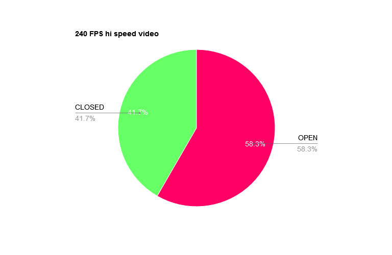
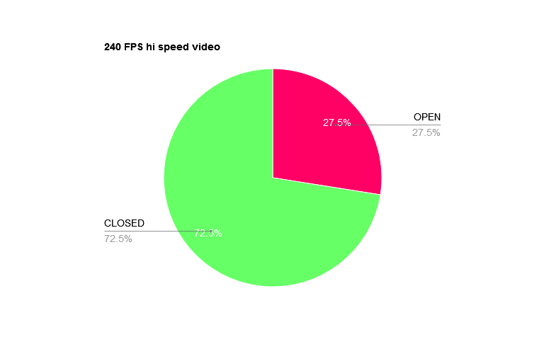
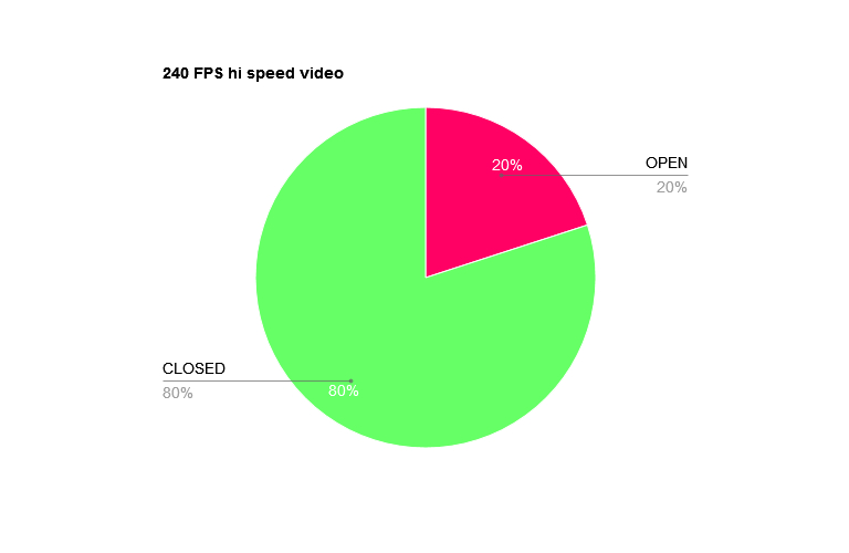
Speeds expressed as % of full shutter. Open RED, closed Green. Speeds 1, 2 and 3.

More on ND filters reading here

Wedge tests galore on optical printer

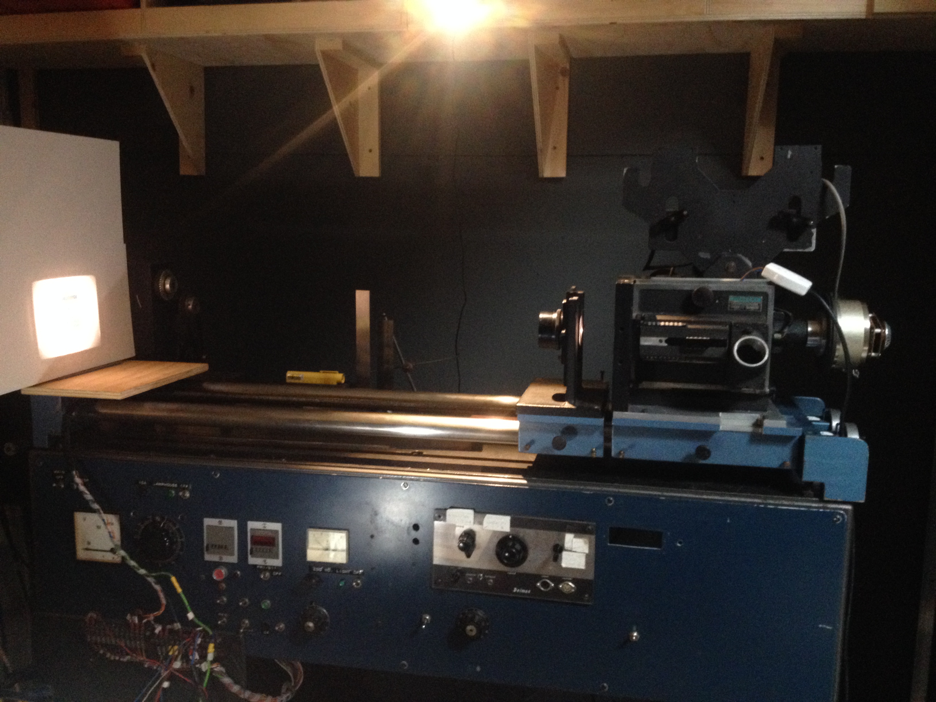
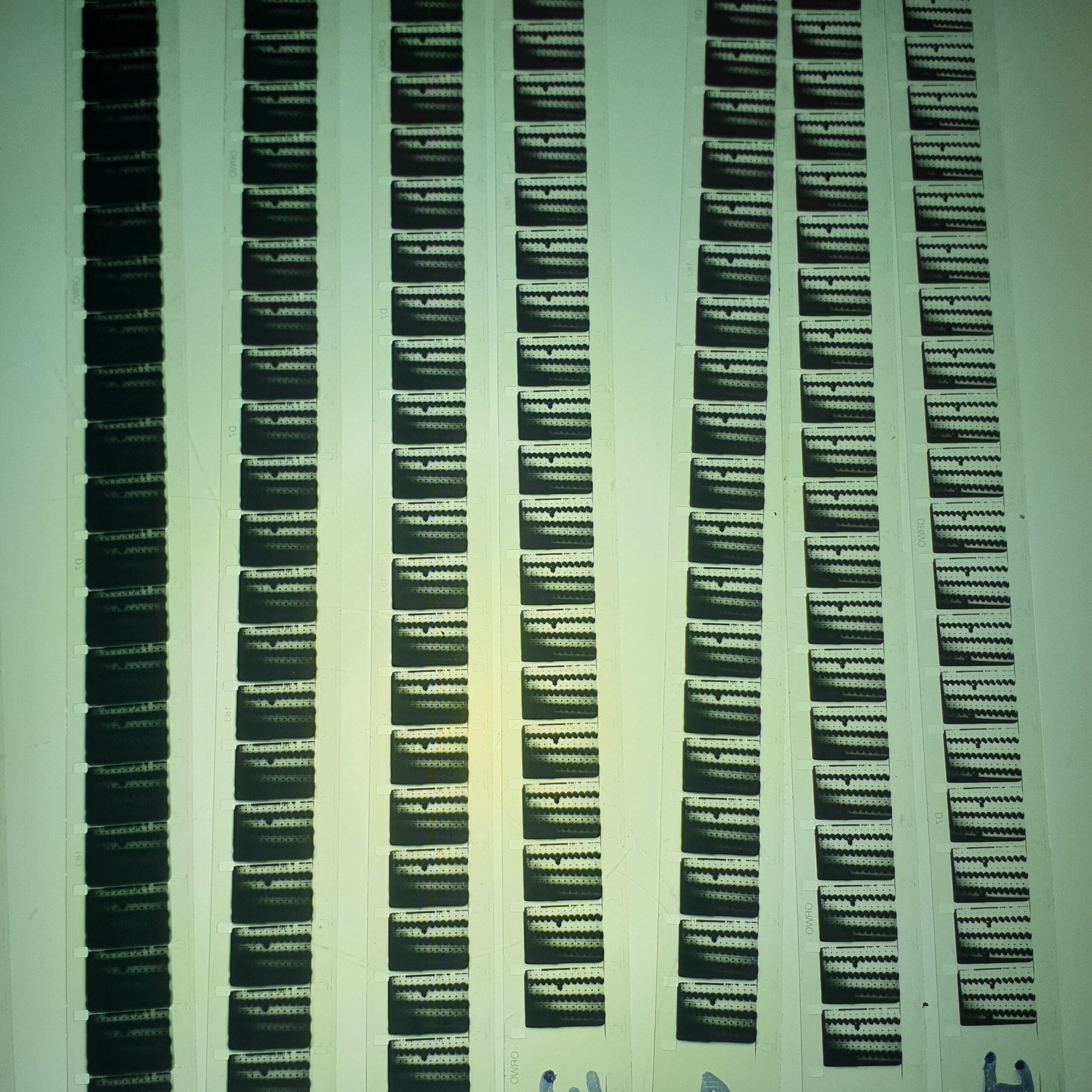
So after finally setting the lens stage and getting the camera drive working I’ve been conducting tons of tests to ascertain exposure settings for different stocks, processes and target outcomes. The first is really to get a good method established for printing negatives to PF2 and 3302 using accurate & repeatable D97 processing.

As the original materials I have to use are themselves also varied interms of calibrated or reference its a matter of getting a quick ‘acceptable’ result, taking into consideration the nature of the original, and aiming at shooting at T5.6 or T8 and then taking a lux measurement in the gate, with transmission through the target, to enable setting up a quick wedge test for any material going to the stocks mentioned above.

Once I have a good density positive at the lens mid point, further tests can be done with shutter angle and ND filters to tweeak the results plus of course processing factors such as dev time and contrast etc.

Its amazing how much light you have to stop down to get results in range. I am lacking a decent set of ND filters so am busy making these from glass squares. (lighting gel is fine, dont need expensive camera filters).

I’ve loaded the camera with 400ft and just snip after the sprockets after each test. That way I can respool, move fogged frames out of the camera and be ready for another test very quickly.

It’s crucial to process D97 accurately and repeatable for tests. Tweaking this stage comes later when chasing specific effects.

Also its super important to log and document each test, what each tests carries out as this info is needed after to determine which factors are responsible for which samples. For instance in one test there was a few flash frames where the image looked good, better even then the tests, but it was somekind of accident as it didn’t follow my test sequence. I dont know what happened so cant repeat it.

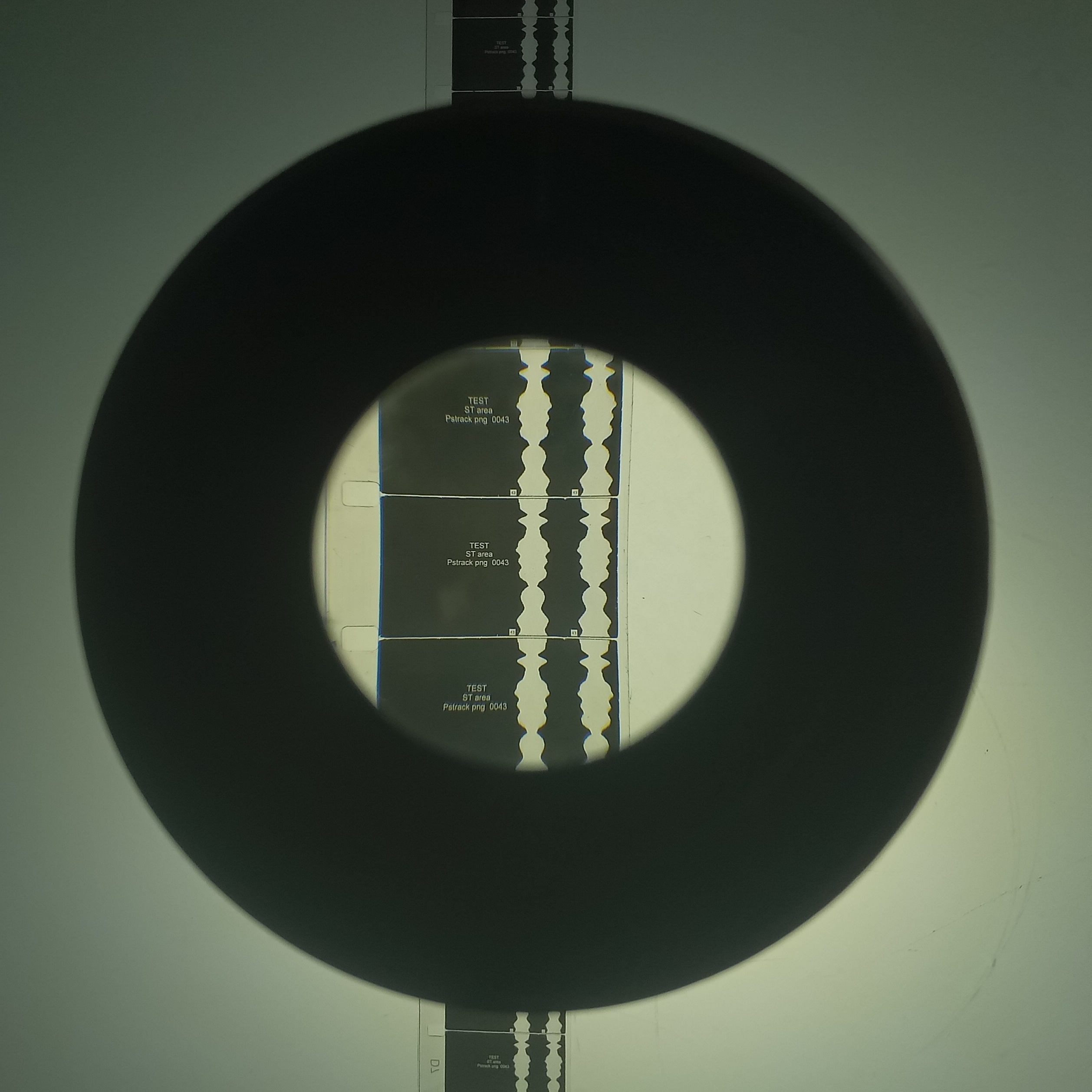
Im shooting a single frame Ive chosen for a few reasons. Its not helpful that I am copying a neg that is itself actually on Agfa ST8D, a hi-con sound track stock. The image is sharp, but will not produce a full range of greys. However, Im after a subjectively good looking result so it doesnt matter. Other tests can be done shooting negatives in controlled conditions to generate reference material.

I have of course unconvered some new annoying issues such as the fact that the viewfinder glass does not seem to correspond to the camera gate, which if true is disastous and may need lengthy rectification. On the whole though the whole system is coming on well and for once Im too busy to get around to uploading this blog.

Cabin in the woods

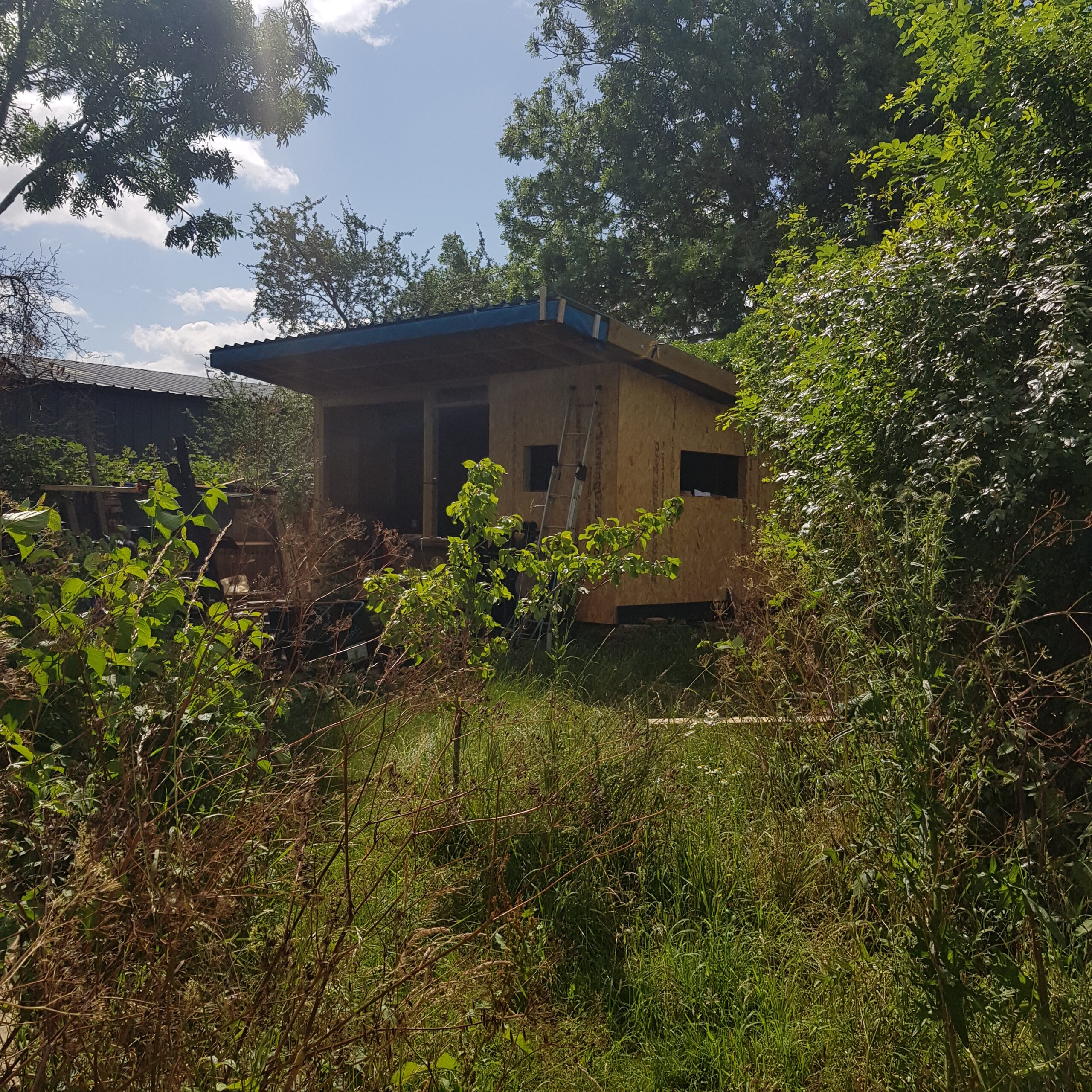
Well, cabin in the corner of the garden anyway. Trying to crack on with this so that anyone who wants to come and work at Asylum or my studio can stay here. Anyone who doesn’t want to work here can stay as well because that is what friends are for. It will have double bed, woodstove, a fax line, morse code terminal and electrification. Guests can use the house WC and the plan is to build an outside kitchen and traditional Cob oven. Im naming it ‘The Library’ because I’m ging to fill it with books, 95% of which are about cinema apparatus, film theory, experimental film and the other 5% is about Toads.

Sync loops

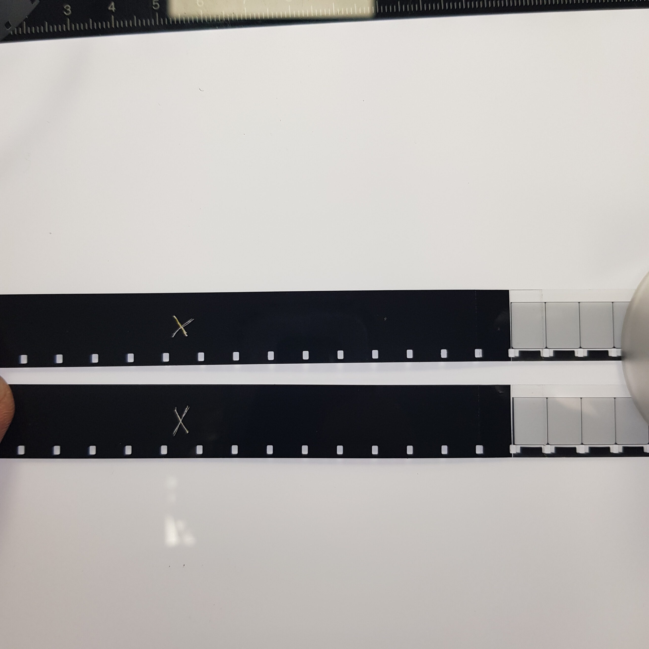
To see if the sync 16mm system worked I made up two identical loops with the exact same frame marked. Amazing when it worked but slightly dissappointing when it didn’t.

Blank wall of Nothing

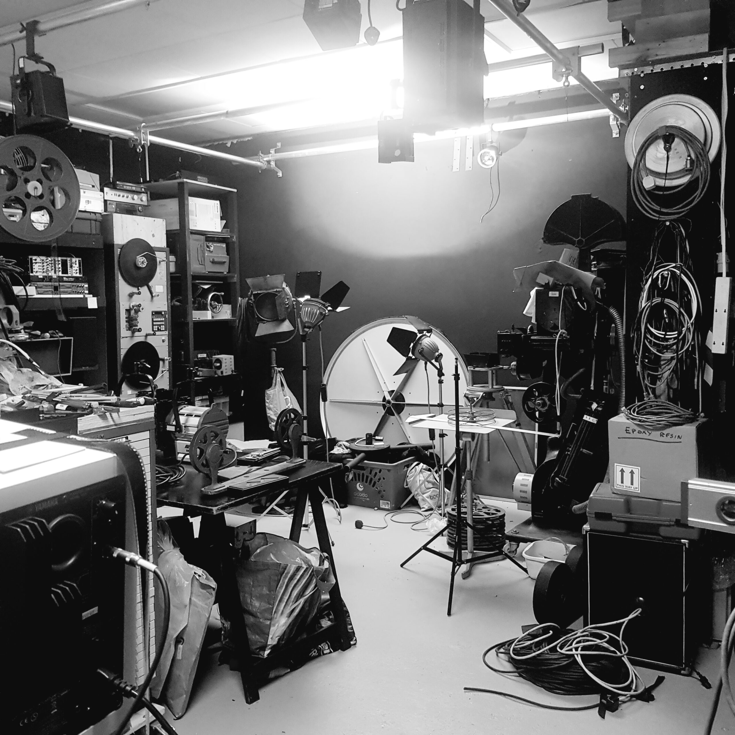
The whole of the workshop/studio has been planned around an central, empty space and a free wall. Everything like filing cabinets, sets of drawers, storage has been bult on wheels so can move out into the corridoor for more room. I finished the overhead scaff riggin the other week for lights and flags. Few more tasks on some machines then I can start making things.

Tidyed up sound – edit area

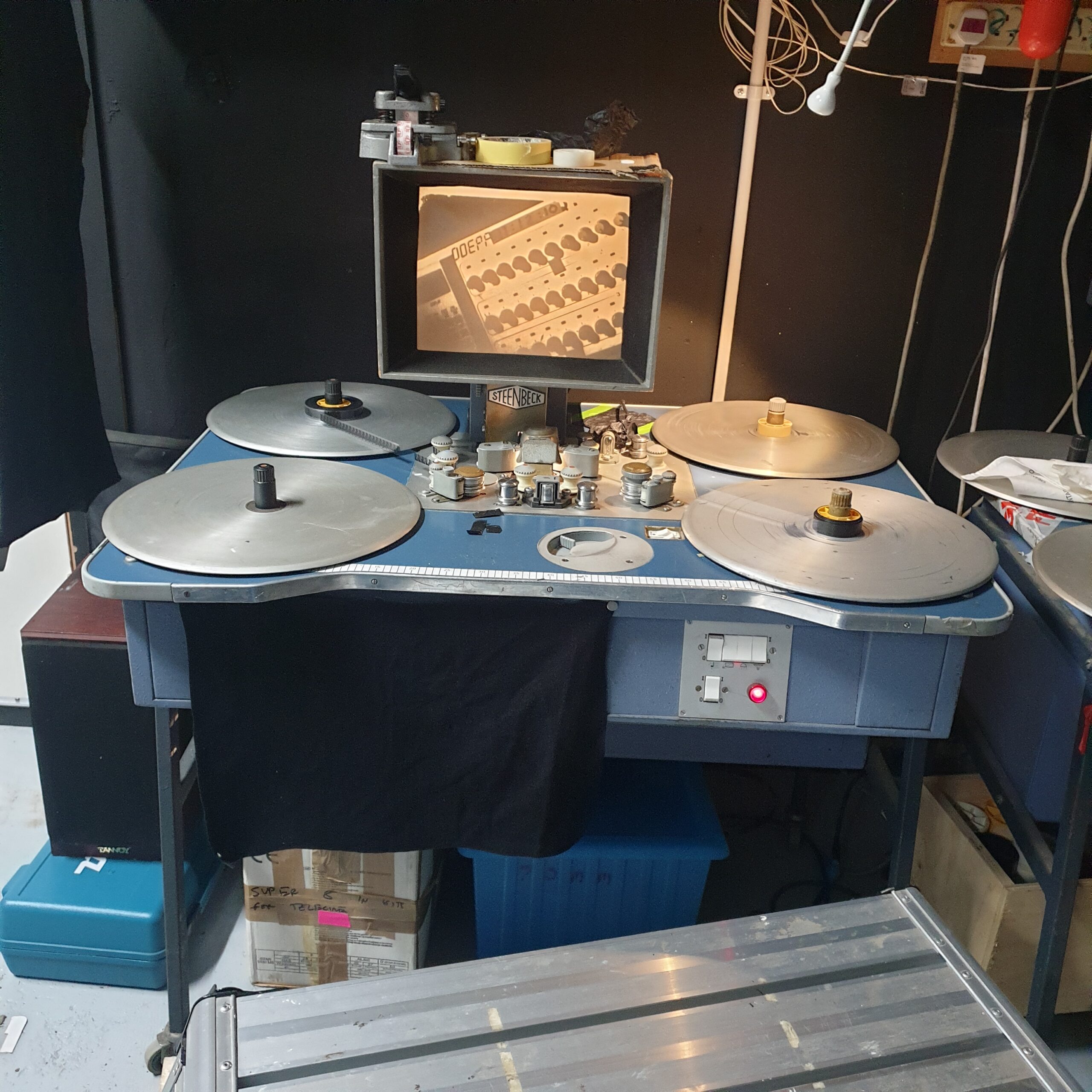
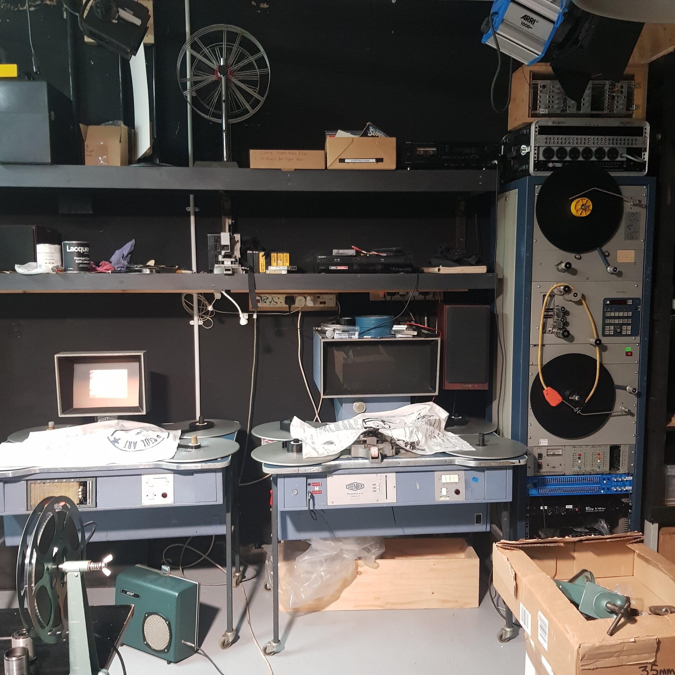
I made use of the Mag follower by using its 19″ racking for the amps and Eqs, for the sound from both the steenbecks. Keeping this area tidy and free of cllutter is crucial when editing material gets hectic.